1592025700 IPROFAMILY 3.5 stp GB 2016.12.07 iPro Series 19/96
Digital relay outputs (for digital outputs with live contacts)
3 NO relays, 1 common and 2 potential free (Neutral)
Digital relay outputs (for digital outputs with potential free contacts)
5 NO relays, 1 common
Digital relay outputs (for digital outputs with live contacts)
5 NO relays, 1 common and 2 potential free (Neutral)
2 NO relays, 1 common
Digital relay outputs (only for 215D versions)
5 NO relays, 1 common and 1 potential free (Neutral)
Green LED to indicate the presence of power
Jumper to activate the RESCUE MODE
Yellow status LEDs (LED1) and red LED (ALARM)
See relative paragraph
Connector for NC contact to reset an external modem
RS232 connector for an external GSM modem connection (SIEMENS TC35)
Connector for an internal analogue modem
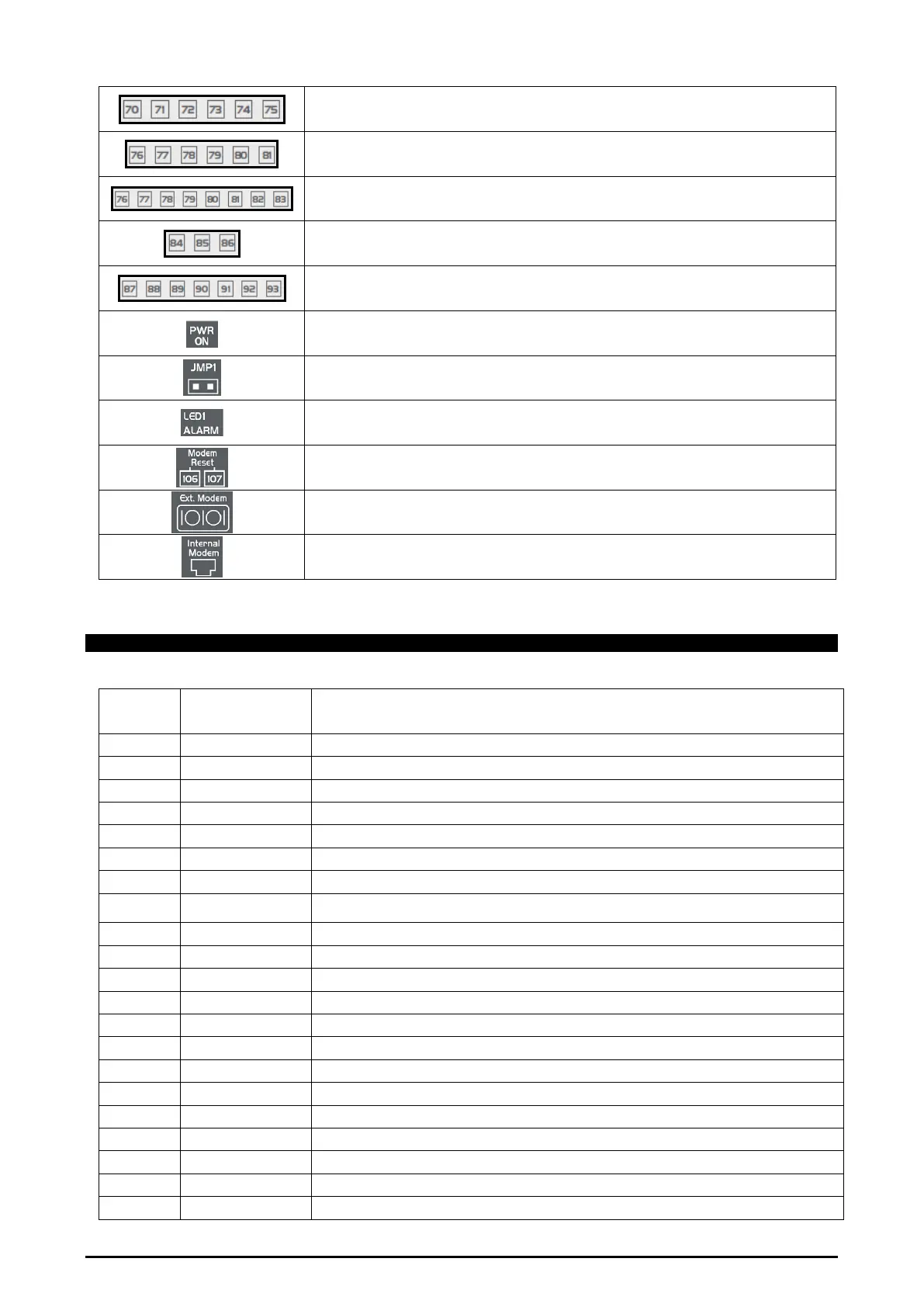
4.2.2 Description of the inputs and outputs
Input
No.
Type of Input Description
1 Supply Reference “-“/GND power (24Vac or 24Vdc)
2 Pb1 Configurable analogue input 1 (NTC, PTC, 0 - 20mA, 4 - 20mA, 0 - 10V, 0 - 1V, 0 - 5V, DI)
3 Pb2 Configurable analogue input 2 (NTC, PTC, 0 - 20mA, 4 - 20mA, 0 - 10V, 0 - 1V, 0 - 5V, DI)
4 Pb3 Configurable analogue input 3 (NTC, PTC, 0 - 20mA, 4 - 20mA, 0 - 10V, 0 - 1V, 0 - 5V, DI)
5 Pb4 Configurable analogue input 4 (NTC, PTC, 0 - 20mA, 4 - 20mA, 0 - 10V, 0 - 1V, 0 - 5V, DI)
6 Pb5 Configurable analogue input 5 (NTC, PTC, 0 - 20mA, 4 - 20mA, 0 - 10V, 0 - 1V, 0 - 5V, DI)
7 PbC Common analogue inputs (NTC, PTC, DI)
8 GND(-)
Additional power reference 5Vdc and 12Vdc and analogue inputs (0 - 20mA, 4 - 20mA, 0 -
10V, 0 - 1V, 0 - 5V)
9 Supply Reference “+“ power supply (24Vac or 24Vdc)
10 Pb6 Configurable analogue input 6 (NTC, PTC, 0 - 20mA, 4 - 20mA, 0 - 10V, 0 - 1V, 0 - 5V, DI)
11 Pb7 Configurable analogue input 7 (NTC, PTC, 0 - 20mA, 4 - 20mA, 0 - 10V, 0 - 1V, 0 - 5V, DI)
12 Pb8 Configurable analogue input 8 (NTC, PTC, 0 - 20mA, 4 - 20mA, 0 - 10V, 0 - 1V, 0 - 5V, DI)
13 Pb9 Configurable analogue input 9 (NTC, PTC, 0 - 20mA, 4 - 20mA, 0 - 10V, 0 - 1V, 0 - 5V, DI)
14 Pb10 Configurable analogue input 10 (NTC, PTC, 0 - 20mA, 4 - 20mA, 0 - 10V, 0 - 1V, 0 - 5V, DI)
15 +5V Additional power +5Vdc
16 +12V Additional power +12Vdc
21 Out1 Opto-insulated analogue output 1 0 - 10V
22 Out2 Opto-insulated analogue output 2 0 - 10V
23 Out3 Opto-insulated analogue output 3 0 - 10V
24 Out4 Opto-insulated analogue output 4 0 - 10V
25 GND(-) Common opto-insulated analogue output