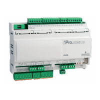
1592025700 IPROFAMILY 3.5 stp GB 2016.12.07 iPro Series 51/96
4.8.2 Description of the inputs and outputs
Input Type of Input Description
1 Supply Reference “-“/GND power (24Vac or 24Vdc)
2 Pb1
Configurable analogue input 1 (NTC, PTC, PT1000, 0 - 20mA, 4 - 20mA, 0 - 5V, 0 - 1V, 0 -
10V, DI, not used)
3 Pb2
Configurable analogue input 2 (NTC, PTC, PT1000, 0 - 20mA, 4 - 20mA, 0 - 5V, 0 - 1V, 0 -
10V, DI, not used)
4 Pb3
Configurable analogue input 3 (NTC, PTC, PT1000, 0 - 20mA, 4 - 20mA, 0 - 5V, 0 - 1V, 0 -
10V, DI, not used)
5 Pb4
Configurable analogue input 4 (NTC, PTC, PT1000, 0 - 20mA, 4 - 20mA, 0 - 5V, 0 - 1V, 0 -
10V, DI, not used)
6 Pb5
Configurable analogue input 5 (NTC, PTC, PT1000, 0 - 20mA, 4 - 20mA, 0 - 5V, 0 - 1V, 0 -
10V, DI, not used)
7 +12V Additional power +12Vdc
8 ID Common for digital inputs from 1 to 3 when power supply (24Vac/dc)
9 Supply Reference “+“ power supply (24Vac or 24Vdc)
10 DI1 Digital input 1 (potential free contact (13) or power supply (8))
11 DI2 Digital input 2 (potential free contact (13) or power supply (8))
12 DI3 Digital input 3 (potential free contact (13) or power supply (8))
13 DIC Common for digital inputs from 1 to 3 when potential free
14 Pbc Common analogue inputs (NTC, PTC, PT1000, DI)
15 GND(-)
Additional power reference 5Vdc and 12Vdc and analogue inputs (0 - 20mA, 4 - 20mA, 0 -
10V, 0 - 1V, 0 - 5V)
16 +5V Additional power +5Vdc
20 GND(-) Additional power reference 5Vdc, 12Vdc and analogue outputs
21 Out1 Analogue output 1 0 - 10V
22 Out2 Analogue output 2 0 - 10V
23 Out3 Analogue output 3 0 - 10V
24 Pb6
Configurable analogue input 6 (NTC, PTC, PT1000, 0 - 20mA, 4 - 20mA, 0 - 5V, 0 - 1V, 0 -
10V, DI, not used)
25 GND(-) Additional power reference 5Vdc, 12Vdc and analogue outputs
26 +12V Additional power +12Vdc
27 +5V Additional power +5Vdc
28 Pbc Common analogue inputs (NTC, PTC, PT1000, DI)
29 Pb7
Configurable analogue input 7 (NTC, PTC, PT1000, 0 - 20mA, 4 - 20mA, 0 - 5V, 0 - 1V, 0 -
10V, DI, not used)
30 CAN Bus CAN Bus connection (+), not open
32 CAN Bus CAN Bus connection (-), not open
33 CAN Bus CAN Bus connection (gnd), not open
35 LAN LAN connection (+)
36 LAN LAN connection (-)
60 RL1 Relay 1 normally open contact
61 C Common relays 1 and 2 (MAX 5A)
62 RL2 Relay 2 normally open contact
63 RL3 Relay 3 normally open contact
64 C Common relays 3 and 4 (MAX 5A)
65 RL4 Relay 4 normally open contact
66 C Common relay 5 (please check the electrical characteristics of the relay used )
67 RL5 Relay 5 normally open contact (please check the electrical characteristics of the relay used )
68 NU Not used
69 RL6 Relay 6 normally closed contact
70 RL6 Relay 6 normally open contact
71 C Common relay 6 (MAX 8A)
 Loading...


