1592025700 IPROFAMILY 3.5 stp GB 2016.12.07 iPro Series 61/96
4.10 IPX215D – IPX225D
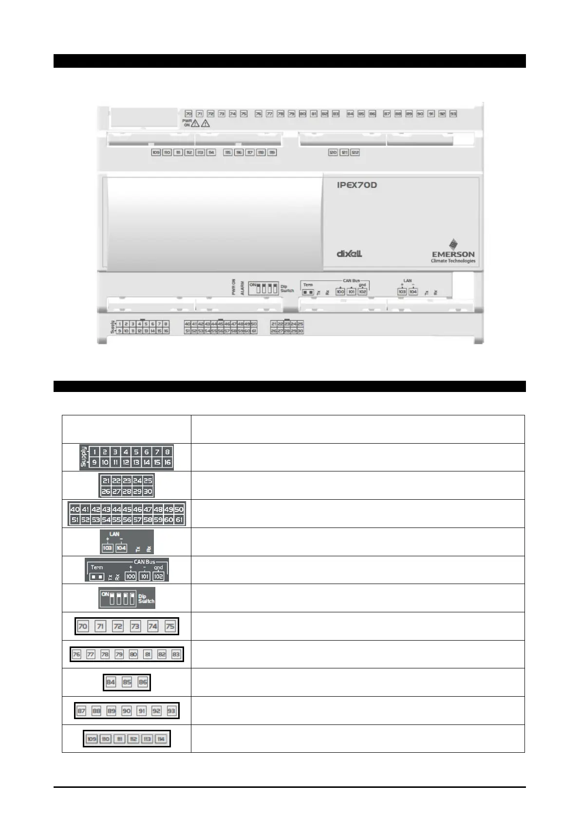
4.10.1 Description of the connections
Connector Description
Connector for 24Vac/dc power supply
Analogue inputs (Pb1 - Pb10, PbC)
Additional power (+5Vdc, +12Vdc, GND)
Opto-insulated analogue outputs (Out1 - Out6, GND)
24Vac/dc power supply for the opto-insulated analogue output
Potential free opto-insulated digital inputs (DI1 - DI20, DIC)
Opto-insulated 24Vac/dc digital inputs (DI1 - DI20, GND)
LAN serial port connector
Rx and Tx LED to indicate that communication is active
Rx and Tx LED to indicate that communication is active
Dip-switch to set the address of the device.
3 NO relays, 1 common and 2 potential free (Neutral)
5 NO relays, 1 common and 2 potential free (Neutral)
2 NO relays, 1 common
5 NO relays, 1 common and 1 potential free (Neutral)
The position 93 is not connected
Digital outputs with SSR relays
4 NO relays, 1 common
The position 109 is not connected