19
Reference Manual
00809-0100-4840, Rev CB
Section 3: Installation
February 2015
Installation
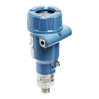
Relays
The 3102 has two integral relays which may be used for fault indication or control purposes.
These relays are for light duty and should be used as signal relays only, with control functions
being performed by external control relays.
Relay number 2 is defaulted as a 'fault' relay - normally energized - but may be re-configured
on-site as a set-point relay if required.
Relay status indicators are on the LCD inside the housing (see “Integral display and buttons” on
page 24).
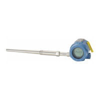
3.4.4 Connecting the cable wires to the Rosemount 3105
The Rosemount 3105 is for intrinsically safe installations. See Appendix B: Product Certifications
for the safety approvals and control drawings.
Important
Make sure the power supply is off when connecting the transmitter
Installation in a non-hazardous (ordinary location) area
Wire the transmitter as shown in Figure 3-10 on page 20.
Installation in a hazardous area
When the 3105 is powered by a Rosemount 3490 Series Control Unit, no safety barriers are
required as the output from the control unit is Intrinsically Safe.
If powering the transmitter from any other power supply, ensure a suitable Intrinsically Safe
barrier is fitted in the non-hazardous (safe) area.
The barrier must be chosen such that its output parameters Uo, Io and Po are less than Ui, Ii and
Pi of the transmitter (see Appendix B: Product Certifications).
The sum of the capacitance and the inductance of the transmitter and the connecting cable
fitted must not exceed the maximum specified for the barrier chosen.
Note
Make sure that the instruments in the loop are installed according to intrinsically-safe field
wiring practices and control drawings, when applicable
If HART digital communications is required, see also “Wiring to allow HART communications”
on page 21.

 Loading...