148 CG Drives & Automation 01-7492-01r1
Normal Load [41B]
Set the level of the normal load. The alarm or pre alarm will
be activated when the load is above/under normal load ±
margin.
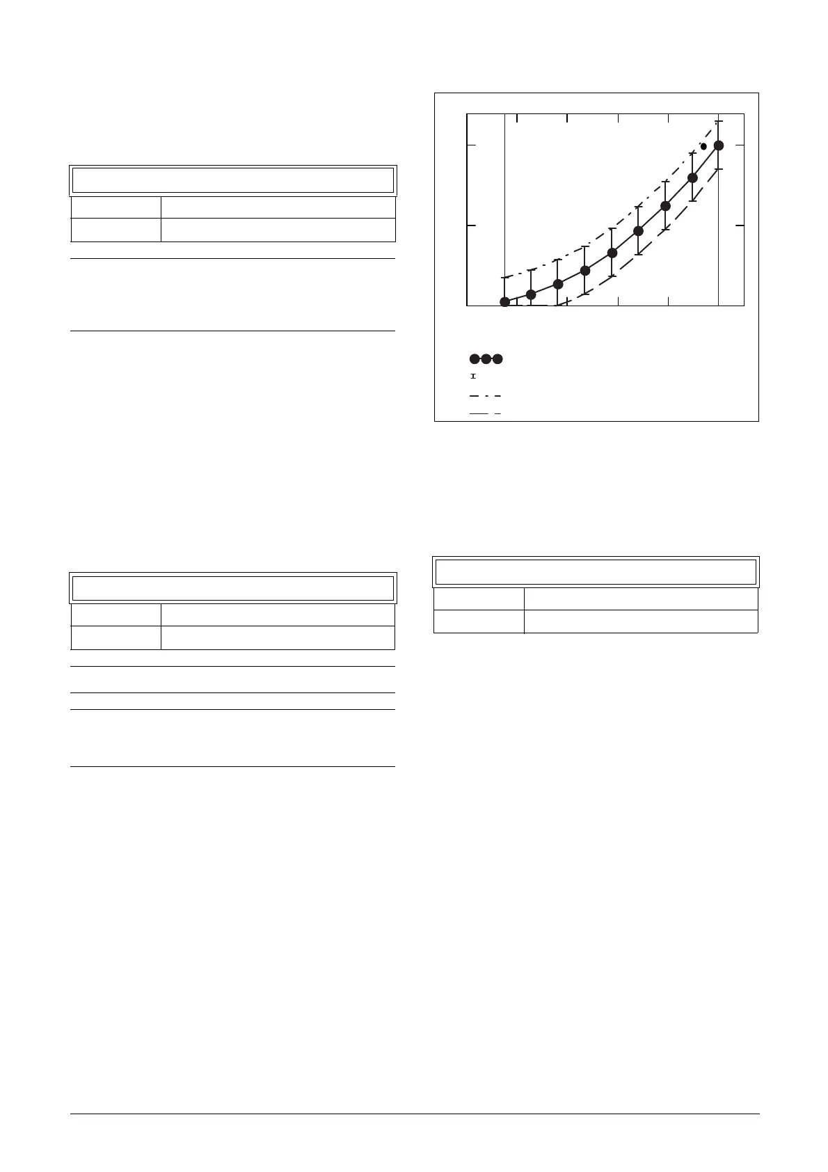
Load Curve [41C]
The load curve function can be used with any smooth load
curve. The curve can be populated with a test-run or the
values can be entered or changed manually.
Load Curve 1-9 [41C1] - [41C9]
The measured load curve is based on 9 stored samples. The
curve starts at minimum speed and ends at maximum speed,
the range in between is divided into 8 equal steps. The
measured values of each sample are displayed in [41C1] to
[41C9] and can be adapted manually. The value of the 1st
sampled value on the load curve is displayed.
Fig. 122
Minimum Absolute Margin [41D]
This menu is displayed when using “Load Curve R”
Set absolute minimum margin of the Load Curve in % of
nominal motor torque.
41B Normal Load
Default: 100%
Range: 0-400% of max torque
NOTE: 100% Torque means: I
NOM
= I
MOT
. The
maximum depends on the motor current and AC drive
max current settings, but the absolute maximum
adjustment is 400%.
41C1 Load Curve1
Default: 100%
Range: 0–400% of max torque
NOTE: Speed signals are limited to < 32767.
NOTE: The speed values depend on the Min- and
Max Speed values. they are read only and cannot be
changed.
41D MinAbsMarg
Default: 3 %
Range: 0 - 31 %
0 0.2 0.4 0.6 0.8 1
0
0.5
1
Min Speed
Speed
Max Speed
Min-Max alarm tolerance band graph
Measured load samples
Min-max tolerance band
Max alarm limit
Min alarm limit

 Loading...

