CG Drives & Automation 01-7492-01r1 Installation 37
Emotron VFX48-090 mount extra ferrite
core
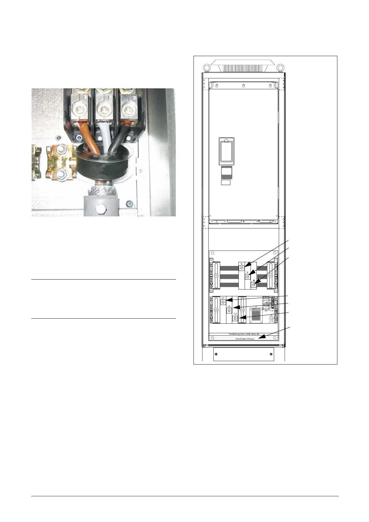
Mount the ferrite core and its isolation sheet (included in
the delivery) on the three motor phases U,V &W.
The protective earth (PE) and the screen of the cable should
be mounted outside the core see fig. 55.
Fig. 55 Ferrite core mounted on the motor cables
The ferrite core is mounted on the motor cable to reduce
disturbances and to fulfil the EMC standards. Since the core
becomes very hot, the cables must be protected by a thermal
isolation sheet that is attached on the core. The longer
motor cables the hotter the core becomes.
AC drive model 48-430 and 69-250 and up
Fig. 56 Connect motor cables and mains cables to the
terminals and earth/ground to the bus bar.
AC drive models 48-430 and 69-250 and up are supplied
with power clamps for mains and motors. For connection of
PE and earth there is a grounding bus bar.
For all type of wires to be connected the stripping length
should be 32 mm (1.26 in).
NOTE: If the core is not mounted or mounted
incorrect, the AC drive does not fulfil the EMC
standards. If the protective isolation sheet is not
mounted, the motor cable can be damaged from the
hot core.
Motor connection
U
V
W
Mains Connection
L1
L2
L3
Ground / earth
connection
bus bar

 Loading...

