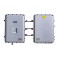
SS500e/SS2000e/SS3000e Analyzer
Index–2 4900002230 rev. D 2-6-20
L
Laser beam 1–5
Laser output fluctuations 1–6
Leak detector 3–20
, B–2
Lens cleaning cloth B–3
, B–6
Lock-in amplifier 1–7
M
Mating terminal block 3–12, 3–17
Membrane separator B–2
Mirror contamination 1–7
, B–2, B–3
N
Natural frequencies 1–5
O
Optional analyzer hood 3–3
Outline schematic A–12
, A–13, A–14,
A–15
Output Signal
4-20 mA current loop 3–11
Digital outputs 3–11
Serial output 3–11
P
Parameters
Measurement and control
4 mA Value 3–18
4-20 mA % Test 3–18
4-20 mA Alarm Action B–20
,
B–21
Port
Sample inlet 3–19
Sample return 3–20
Sample supply 4–8
Power terminal box 3–8
Pressure regulator 4–1
, 4–7, 4–8, 4–9,
4–11, 4–12
Purge system 1–4
Purging 1–4
R
Raw data 1–6
Reference gas 1–4
Resonances
Natural frequencies
S
Sample 1–4
Sample bypass 4–7
, 4–9, 4–10, 4–11,
4–12
Sample bypass stream
Start up 4–7
Sample cell B–1
Sample Conditioning System (SCS) 1–4
,
4–1, B–6, B–7
Periodic maintenance B–16
Preventative and demand
maintenance B–16
Sample gas 1–5
Sample probe 4–1
, 4–5, 4–6, 4–7, 4–9,
4–11
Serial cable 3–12
Serial connection 3–11
, 3–12
Service contact B–23
Shutdown analyzer
Short-term 4–10
Signal wires 3–12
SS3000e
Dual stream
Outline and mounting
dimensions A–12
Power and signal wiring A–15
Sample system schematic A–13
,
A–14
Single stream
Outline and mounting
dimensions A–9
power and signal wiring A–11
Sample system schematic A–10
SS500e/SS2000e
Outline and mounting dimensions A–6
Power and signal wiring A–8
Sample system schematic A–7
Stainless steel tubing 3–19
, B–1
STL8 (conduit lubricant) 3–10
System models 1–4
SS2000e 1–4
SS3000e 1–4
SS500e 1–4
T
Temperature controller
Electric tracer 4–6
Too l s 3–3
Tools and supplies B–3
Trace gas measurement (mixed
background) 1–8
Tracer 4–6
Tunable diode laser (TDL) 1–4
Tunable diode laser absorption
spectroscopy (TDLAS) 1–5

 Loading...


