LEDs
Enterasys S-Series Stand Alone (SSA) Hardware Installation Guide 3-3
Table 3‐2describestheLEDindicationsfortheRXandTXLEDswhentheRJ45portsareinPoE
mode.YoucanswitchtheRJ45portstoPoEmodeorRX/TXmodebypressingtheredPOEbutton
intheupperrightcorneroftheSSA.ThePOELED,describedin
Table 3‐3,indicateswhetherthe
RJ45portLEDsareinPoEorRX/TXmode.
System LEDs
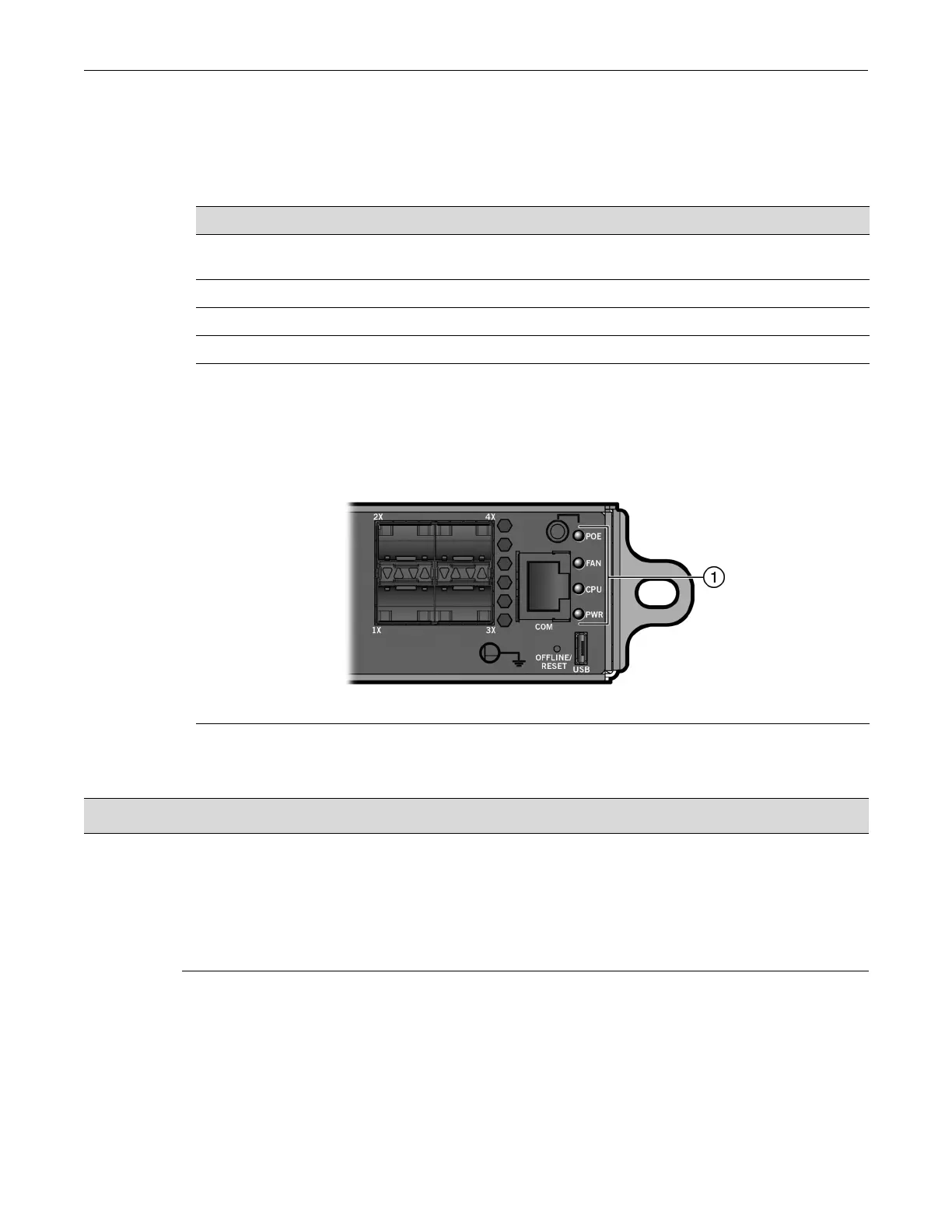
Figure 3‐3showstheSSAsystemLEDs.
Figure 3-3 SSA System LEDs
Table 3‐3describestheLEDindicationsforthesystemLEDsandprovidesrecommendedactions.
Table 3-2 RJ45 Port LEDs—PoE Mode
RX LED Color TX LED Color State
Green None There is a connection to the PD and there is 48VDC at the RJ45
connector.
None Yellow Port is off due to overload (attached PD exceeded maximum load).
Yellow None Port is off due to PoE power management.
None None Port is off due to another reason.
1 SSA system LEDs
Table 3-3 System LEDs
LED Color State Recommended Action
POE Green The RJ45 port LEDs are in PoE mode. See
Table 3-2. You can switch to or from PoE
mode by pressing the red POE button next
to the POE LED.
In PoE mode, the PWR LED indicates the
numbers and types of power supplies
installed.
None.
None The RJ45 port LEDs are in RX/TX mode.
See Table 3-1 on page 3-2. You can switch
to or from RX/TX mode by pressing the red
POE button next to the POE LED.
None.
 Loading...


