Completing the Installation Pin Out Descriptions
2-20 Installation
Adapter Wiring and Signal Assignments
Completing the Installation
AfterinstallingtheSSAandmakingtheconnectionstothenetwork,accessthedevice
managementstartupscreenfromyourPCorterminalconnectionasdescribedinthefollowing
section.
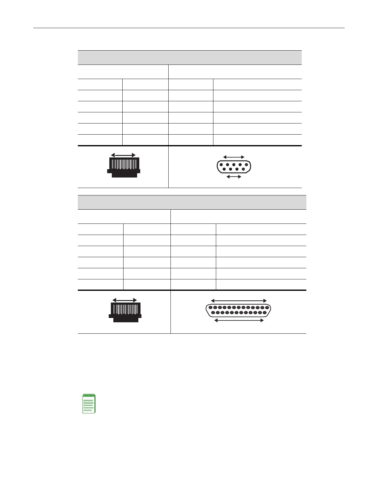
COM Port Adapter Wiring and Signal Diagram
RJ45 DB9
Pin Conductor Pin Signal
1 Blue 2 Receive (RX)
4 Red 3 Transmit (TX)
5 Green 5 Ground (GRD)
2 Orange 7 Request to Send (RTS)
6 Yellow 8 Clear to Send (CTS)
VT Series Port Adapter Wiring and Signal Diagram
RJ45 DB25
Pin Conductor Pin Signal
4 Red 2 Transmit (TX)
1 Blue 3 Receive (RX)
6 Yellow 5 Clear to Send (CTS)
5 Green 7 Ground (GRD)
2 Orange 20 Data Terminal Ready
RJ45 Connector (Female)
Pins
81
69
DB9 Connector
Female
15
Pins
RJ45 Connector (Female)
Pins
81
DB25 Connector (Female)
Pins
25
14
13 1
Note: This procedure applies only to initial log-in and to logging in to a device not yet configured
with administratively-supplied user and password settings.
By default, the SSA is configured with three user login accounts: ro for Read-Only access; rw for
Read-Write access; and admin for super-user access to all modifiable parameters. The default
password is set to blank (null). For information on changing these default passwords, refer to the
Enterasys S-Series Configuration Guide.
 Loading...


