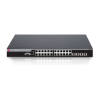
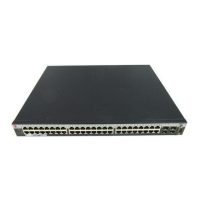
Replacing the SSA Fans
Enterasys S-Series Stand Alone (SSA) Hardware Installation Guide 3-11
6. To ensureproperairflow,connectthenewfantothechassisconnectorwiththelabelsideof
thereplacementfanfacingintotheSSAandthecableclipontheright.SeeFigure 3‐8.
DonotremovethecablecliponfansF1–F7.SeeFigure 3‐9onpage 3‐12,
whichshowsthe
cableclip.
Figure 3-8 Connecting an F1–F7 Fan (Fan F3 Example)
7. Placethefaninthechassisnexttotheconnector.SeeFigure 3‐8.
8. ReinstallthesidepaneloftheSSA.
YoucannowreinstalltheSSAintheequipmentrack.
1 Fan F3 connector 2 Fan F3 (label facing into the SSA)

 Loading...
