Replacing the SSA Fans
3-8 Troubleshooting
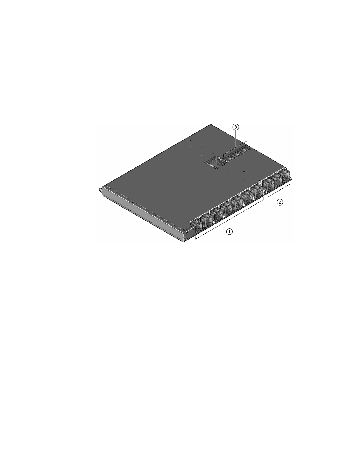
ThethirteenSSAfansaredividedintothreegroups(seeFigure 3‐4):
•FansF1–F7,whicharelocatedontherightsideoftheSSA.EachF1–F7fan’sconnectoris
adjacenttothefan.See“ReplacingFansF1–F7”onpage 3‐9.
•FansF8–F10,which,likefansF1–F7,arelocatedonthe
sideoftheSSA;however,fansF8–F10
donothaveadjacentconnectors—theyarelocatedbehindfanF7.See“ReplacingFansF8–
F10”onpage 3‐12.
•FansF11–F13,whicharelocatedintherearofthe SSA,betweenthepowersupplybays.Like
fansF8–F10,fansF11–F13donothaveadjacentconnectors.
See“ReplacingFansF11–F13”on
page 3‐14.
Figure 3-4 SSA Fan Locations
BeforereplacinganyoftheSSAfans,youmustfirstpowerdowntheSSAand,ifinstalledinan
equipmentrack,removetheSSAfromtherack.
Thereplacementfankit,SSA‐FAN‐KIT,whichyoumustorderseparately,containsone
replacementfan.
1 Fans F1–F7 2 Fans F8–F10 3 Fans F11–F13
 Loading...


