Replacing the SSA Fans
3-16 Troubleshooting
b. Removethefailedfan’scablesfromtherubbergrommet.
Youmayhavetolifttherubbergrommetoutofthechassistoremovethefailedfan’s
cablesfromthegrommet.Thegrommetisslit.
c. Disconnectthefanfromtheappropriateconnector.
ThebankofF11–F13connectorsislocatednexttofanF11,
ontheothersideofthesheet
metalwallthatseparatesthepowersupplybaysfromtherestoftheSSA.Ifyouarefacing
towardsthebackoftheSSA,theF11–F13connectorsarearrangedasfollows:
‐ F11connector:leftconnector
‐ F12connector:middleconnector
‐ F13connector:rightconnector
5. Unwindthereplacementfan’scables.
6. Removethecableclipfromthereplacementfan.SeeFigure 3‐9onpage 3 ‐12.
Youmaydiscardthecableclip.
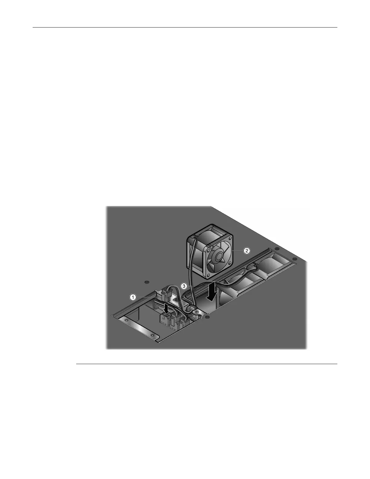
7. Withthelabelsideofthereplacementfanfacingintothesecondpowersupplybay(labeled
PS2)andthecableontheleft,slipthefan
cableintotherubbergrommetandconnectthecable
tothechassisconnector.SeeFigure 3‐14.
Figure 3-14 Connecting an F11–F13 Fan (Fan F11 Example)
8. PositionthefanintheSSA.
9. PositionthecablesoftheF11–F13fansontopofthefans,ensuringthatthecablesarenotina
positionthatwouldcausethecablestobe
pinchedbytherearpanel.
10. ReinstalltherearpaneloftheSSA.
YoucannowreinstalltheSSAintheequipmentrack.
1 Fan F11 connector 2 Fan F11 3 Rubber grommet
 Loading...


