Epson Artisan 700/Epson Stylus Photo PX700W/TX700W Revision C
DISASSEMBLY/ASSEMBLY Disassembly Procedures 118
Confidential
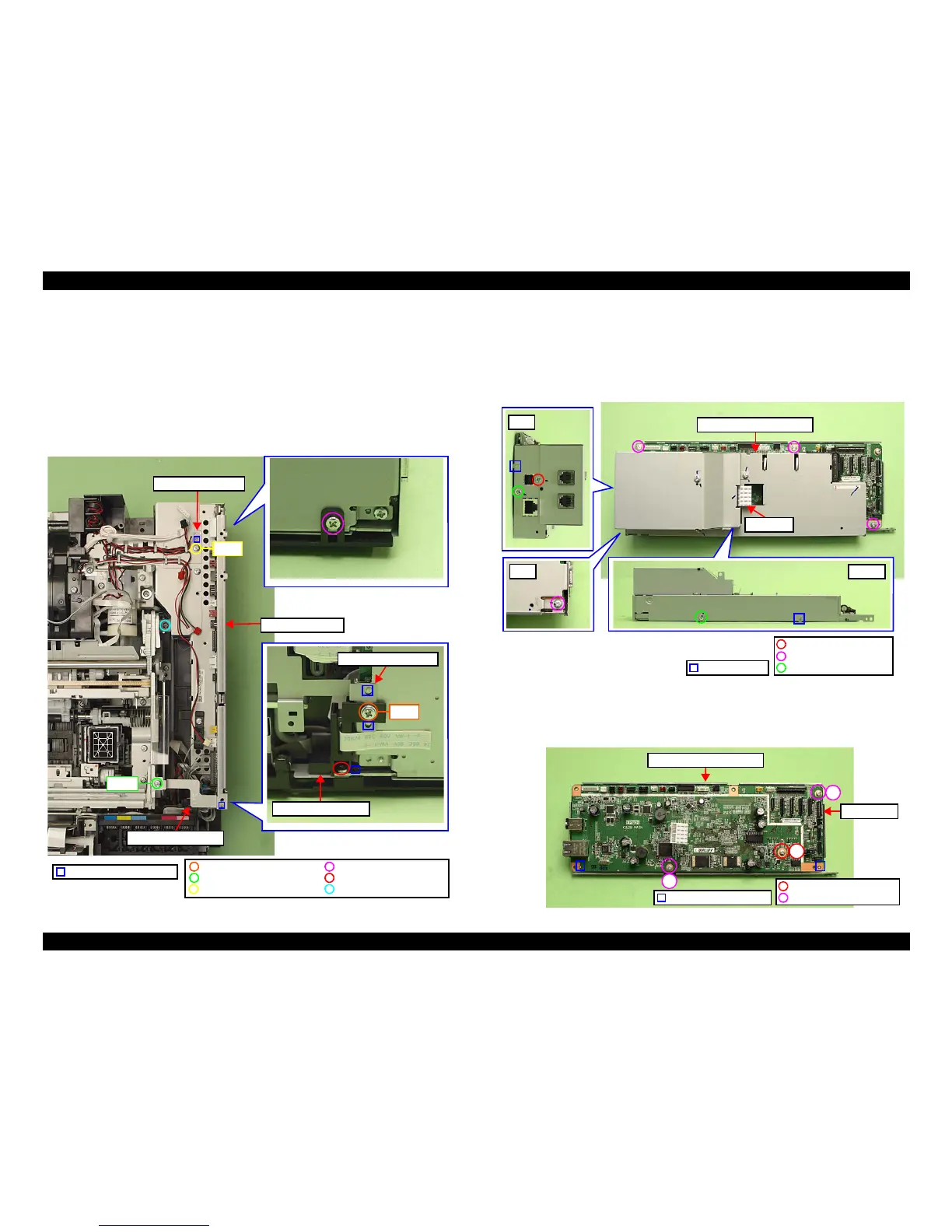
2. Remove the screw (x1) that secures the Right Cable Frame and the Main
Board. (See Fig. 4-40.)
3. Remove the screw (x1) that secures the Ferrite Core Holder A, and remove
the Ferrite Core Ho
lder A. (See Fig. 4-40.)
4. Remove the screw (x1) that secures the Grounding Plate M/B, and remove the
Grounding Plate M/B
. (See Fig. 4-40.)
5. Remove the screws (x3) that secure the Main Board Unit and remove th
e
Main Board Unit.
Figure 4-40. Removing the Main Board Unit
Main Board
1. Disconnect the I/F-B FFC from the FAX board. (Artisan 800/PX800FW/
TX800FW only) (See Fig. 4-41
.)
2. Remove the screws (x7) that secure the Upper Shield Plate M/B, and remove
the Upper Shield
Plate M/B.
Figure 4-41. Removing the Main Board (1)
3. Rem
ove the screws (x3) that secure the Main Board and
remove the Main
Board from the Lower Shield Plate M/B.
Figure 4-42. Removing the Main Board (2)
C.B.P. 3x10 (6±1Kgfcm)
Step 3
Holder IC Shield Plate
Ferrite Core Holder A
C.B.P. 3x8 (6±1Kgfcm)C.B.S. 3x6 (8±1Kgfcm)
C.B.S. 3x6 (6±1Kgfcm)
C.B.S.(P2) 3x8 (8±1Kgfcm) C.B.S. 3x6 (5±0.5Kgfcm)
Step 2
Step 4
Positioning hole & dowel
Right Cable Frame
Main Board Unit
Grounding Plate M/B
Dowel & groove
Rear
Rear
Bottom
Upper Shield Plate M/B
C.B.S. 3x6 (8±1Kgfcm)
C.B.S. 3x6 (4±1Kgfcm)
C.P. 3x6 (4±1Kgfcm)
I/F-B FFC
Positioning hole & dowel
1
2
3
C.B.S. 3x6 (8±1Kgfcm)
C.B.S. 3x10 (8±1Kgfcm)
Lower Shield Plate M/B
Main Board