LX-300+/1170 Revision C
Appendix
onnector Summary
04
7.1 Connector Summary
7.1.1 Major Component Unit
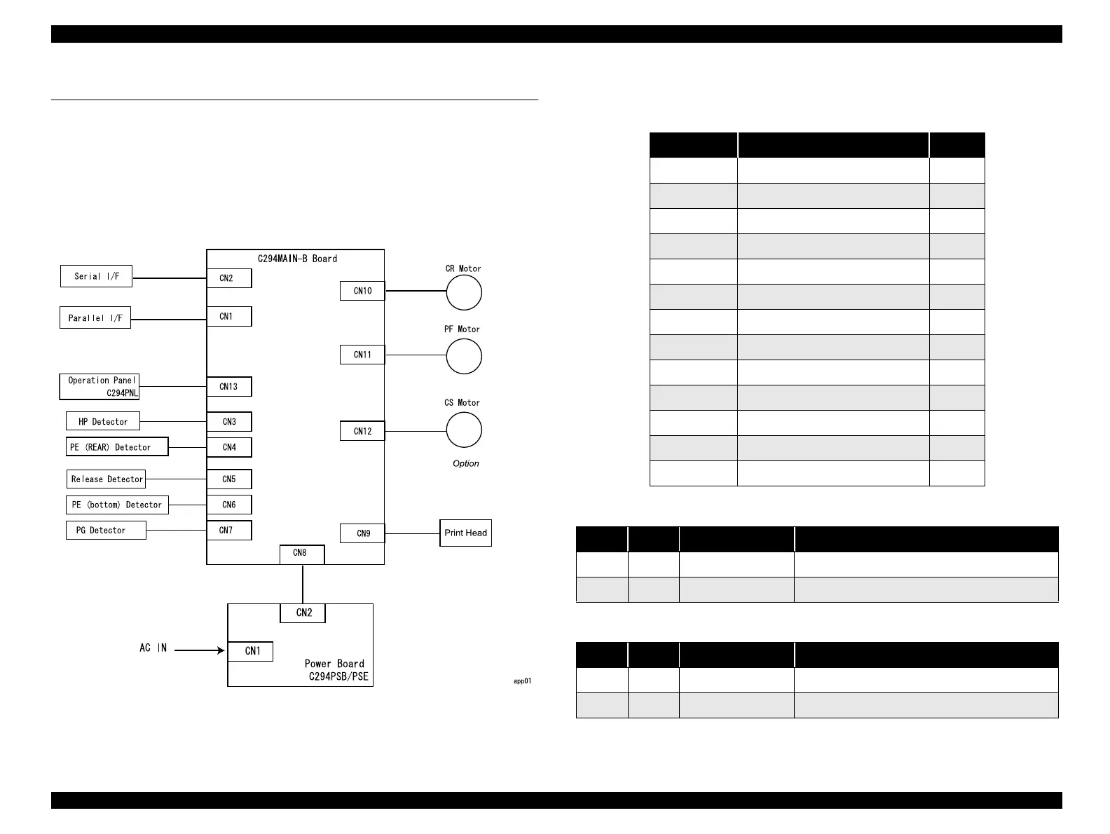
The figure below illustrates how the primary components are connected.
CS motor is only available for LX-300+.
Figure 7-1. Cable Connections
7.1.2 Pin Assignments
Table 7-1. C294MAIN-B Board Connector Summary
Connector Function Pins
CN1 Parallel I/F 36
CN2 Serial I/F 6
CN3 HP Detector 2
CN4 PE (Rear) Sensor 2
CN5 Release Detector 2
CN6 PE (bottom) Detector 2
CN7 PG Detector 2
CN8 Power Board C294PSB/PSE 9
CN9 Printhead 12
CN10 CR Motor 4
CN11 PF Motor 4
CN12 CS Motor (Option) 10
CN13 Operation Panel C294PNL 12
Table 7-2. Connector Pin Assignments - CN3
Pin I/O Signal Name Function
1 I HP Carriage home position sensor signal
2 - GND Signal ground
Table 7-3. Connector Pin Assignments - CN4
Pin I/O Signal Name Function
1 I RPE Rear paper end sensor signal
2 - GND Signal ground

 Loading...