LX-300+/1170 Revision C
Troubleshooting
roubleshooting 67
3.2.4.2 Motor Check
By measuring the direct current resistance of the motor coil, you can check if the motor is
all right.
3.2.4.3 Sensor Check
When the sensor is connected mechanically, you can check the sensor by its conductivity.
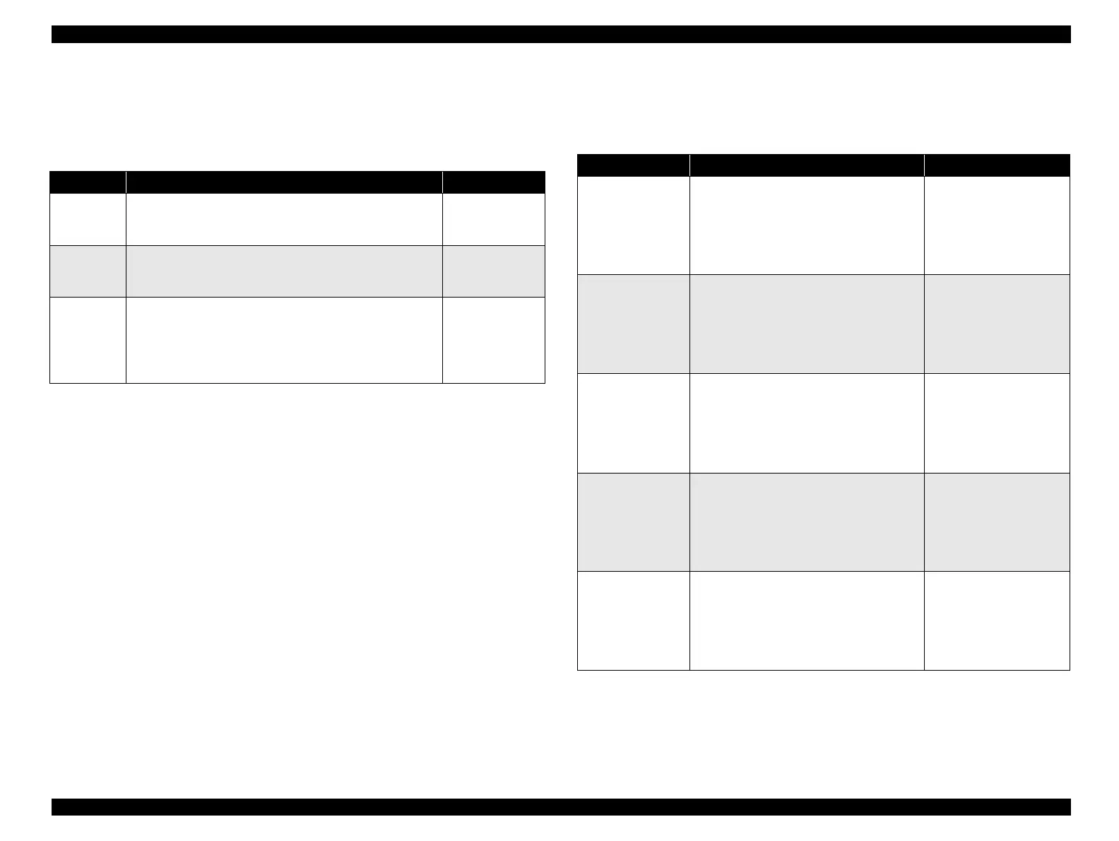
Table 3-11. Motor Check
Item Operation Specification
CR motor
1. Set the multimeter to the resistance measuring range.
2. Connect the one side of the probe to 1 or 2 pin.
3. Connect the other side of the probe to 3 or 4 pin.
5.7Ω ±10%
(at 25°C/phase)
PF motor
1. Set the multimeter to the resistance measuring range.
2. Connect the one side of the probe to 1 or 2 pin.
3. Connect the other side of the probe to 3 or 4 pin.
16.0Ω ±10%
(at 25°C/phase)
CS motor
(option,
LX-300+
only)
1. Disassemble the CS unit.
2. Set the multimeter to the resistance measuring range.
3. Connect the one side of the probe to brown [TBD]
harness.
4. Connect the other side of the probe to other 4 harness.
150Ω ±5%
(at 25°C/phase)
Table 3-12. Sensor Check
Item Operation Specification
HP detector
1. Set the multimeter to the resistance
measuring range.
2. Connect the one side of the probe to
CN3 1 pin.
3. Connect the other side of the probe to
CN3 2 pin.
When switching the
sensor actuator, it should
be switched ON/OFF.
RPE detector
1. Set the multimeter to the resistance
measuring range.
2. Connect the one side of the probe to
CN4 1 pin.
3. Connect the other side of the probe to
CN4 2 pin.
When switching the
sensor actuator, it should
be switched ON/OFF.
Release detector
1. Set the multimeter to the resistance
measuring range.
2. Connect the one side of the probe to
CN5 1 pin.
3. Connect the other side of the probe to
CN5 2 pin.
When switching the
sensor actuator, it should
be switched ON/OFF.
BPE detector
1. Set the multimeter to the resistance
measuring range.
2. Connect the one side of the probe to
CN6 1 pin.
3. Connect the other side of the probe to
CN6 2 pin.
When switching the
sensor actuator, it should
be switched ON/OFF.
PG detector
1. Set the multimeter to the resistance
measuring range.
2. Connect the one side of the probe to
CN3 7 pin.
3. Connect the other side of the probe to
CN3 7 pin.
When switching the
sensor actuator, it should
be switched ON/OFF.

 Loading...