LX-300+/1170 Revision C
PRODUCT DESCRIPTION Interface Specifications 24
1.3.3 Serial Interface
o Synchronization: Asynchronous
o Signal level: EIA-232D
MARK (logical 1): -3V to -25V
SPACE (logical 0): +3V to +25V
o Word length: Start bit: 1 bit
Data bit: 8 bit (LX-300+ only)
Data bit: 8 bit, 7 bit (LX-300+/1170)
Parity bit: Odd, Even, Non, Ignore
Stop bit: 1 bit or more
o Baud rate: 300, 600, 1200, 2400, 4800, 9600 or 19200 bps
o Handshaking: DTR signal and XON/XOFF
DTR=MAEK, XOFF:indicates that the printer cannot
receive data.
DTR=MARK, XON: indicates that the printer is ready
to receive data.
NOTE: The DTR signal is MARK and XOFF code (DC3, 13H) is transmitted
when the rest of the input buffer becomes 256 bytes. The DTR signal is
SPACE and XON code (DC1, 11H) is transmitted when the rest of the
input buffer is regained 256 byte.
o Error handling: Parity error is only detected. Overrun error and
framing error are ignored.
o Connector: 25 pin subminiature D-shell connector (female)
* In/Out shows the direction of signal flow from the printer’s point of view.
17 Chassis -- -- Chassis GND.
16, 33,
19-30
GND -- --
Signal GND.
15, 34 NC -- -- Not connected.
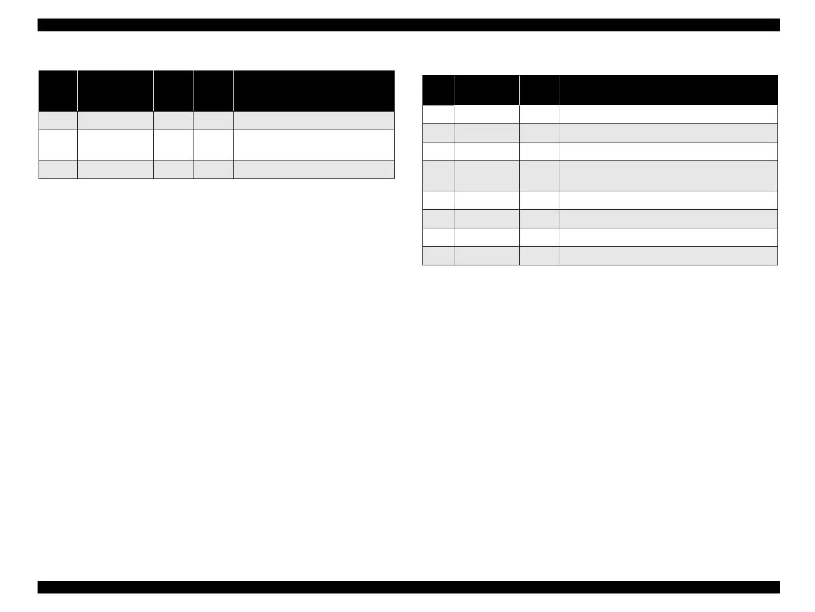
Table1-13. ConnectorPinAssignmentandSignals(ReverseChannel)
Pin No. Signal Name
Return
GND
Pin
In/Out Functional Description
Table 1-14. Connector Pin Assignment and Signals
Pin
No.
Signal Name In/Out Functional Description
2 TXD Out Transmit data.
20 DTR Out Indicates that the printer is ready to receive data or not.
11 REV Out Connected directly to the DTR signal.
4 RTS Out
Request to send. Always SPACE level when the printer
is powered on. Pulled up to +12V via 4.7KΩ resistor.
3 RXD In Receive data.
7 Signal GND -- Signal GND
1 Chassis GND -- Chassis GND
other NC -- Not used. Not connected.

 Loading...