LX-300+/1170 Revision C
PRODUCT DESCRIPTION Interface Specifications 23
1.3.2 Parallel Interface (Reverse Channel)
o Transmission mode: IEEE-1284 nibble mode
o Adaptable connector: See 1.3.1 "Parallel Interface (Forward Channel)"
o Synchronization: Refer to the IEEE-1284 specification
o Handshaking: Refer to the IEEE-1284 specification
o Signal level: IEEE-1284 level 1 device
See 1.3.1 "Parallel Interface (Forward Channel)"
o Data transmission timing: Refer to the IEEE-1284 specification
o Extensibility request: The printer responds to the extensibility request
affirmatively, when the request is 00H or 004H, which means;
00H: Request for nibble mode of reverse channel transfer
04H: Request device ID in nibble mode of reverse channel transfer
o Device ID: The printer sends following device ID string when it is requested.
n
When IEEE1284.4 is enabled;
n
When IEEE1284.4 is disabled;
[00H][4EH]
MFG: EPSON;
CMD: ESCPL2,PRPXL24,BDC,D4;
MDL: LX-300+;
CLS: PRINTER;
DES: EPSON[SP]LX-300+;
[00H][4EH]
MFG: EPSON;
CMD: ESCP9,PRPII9,BDC,D4;
MDL: LX-1170;
CLS: PRINTER;
DES: EPSON[SP]LX-1170;
LX-300+ LX-1170
[00H][4BH]
MFG: EPSON;
CMD: ESCPL2,PRPXL24,BDC;
MDL: LX-300+;
CLS: PRINTER;
DES: EPSON[SP]LX-1170;
[00H][4BH]
MFG: EPSON;
CMD: ESCP9,PRPII9,BDC;
MDL: LX-1170;
CLS: PRINTER;
DES: EPSON[SP]LX-1170;
LX-300+ LX-1170
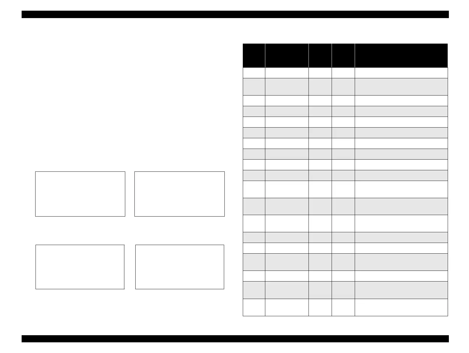
Table 1-13. Connector Pin Assignment and Signals (Reverse Channel)
Pin No. Signal Name
Return
GND
Pin
In/Out Functional Description
1 HostClk 19 In Host clock signal.
2 DATA1 20 In
Parallel input data to the printer.
bit0:LSB
3 DATA2 21 In bit1
4 DATA3 22 In bit2
5 DATA4 23 In bit3
6 DATA5 24 In bit4
7 DATA6 25 In bit5
8 DATA7 26 In bit6
9 DATA8 27 In bit7:MSB
10 PtrClk 28 Out Printer clock signal.
11
PtrBusy/DataBit-
3,7
29 Out
Printer busy signal and reverse channel
transfer data bit 3 or 7.
12
AckDataReq/
DataBit-2,6
28 Out
Acknowledge data request signal and
reverse channel transfer data bit 2 or 6.
13
Xflag/
DataBit-1,5
28 Out
X-flag signal and reverse channel
transfer data bit 1 or 5.
14 HostBusy 30 In Host busy signal.
31 -INIT 30 In Not used.
32
-DataAvail/
DataBit-0,4
29 Out
Data available signal and reverse channel
transfer data bit 0 or 4.
36 1284-Active 30 In 1284 active signal.
18 Logic-H -- Out
Thislineispulledupto+5Vthrough3.9
kΩ resister.
35 +5V -- Out
Thislineispulleduptp+5Vthrough1.0
kΩ resister.

 Loading...