LX-300+/1170 Revision C
Disassembly and Assembly Disassembly and Assembly 80
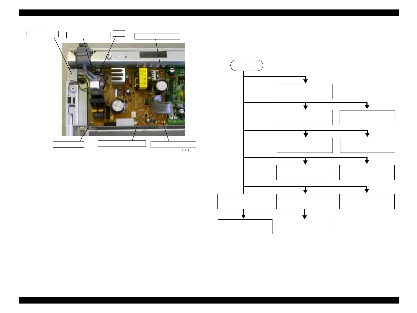
Figure4-9. C294 Power Supply Board Assembly Removal
4.2.7 Printer Mechanism Disassembly
This section explains the disassembling procedure of the printer mechanism. The
disassembling procedure is shown in the flowchart below.
Figure4-10. Printer Mechanism Disassembling Procedure
Power Switch
P/S Board Assembly
CN1
C.B.P., Tite, 3x10 F/ZN
CBP (3x10)
C.B.P., Tite, 3x10 F/ZN
C.B.P., Tite, 3x10 F/ZN
START
4.2.7.10 "PF Motor
Assembly Removal"
4.2.7.2 "Platen
Removal"
4.2.7.9 "Release Lever
Position Sensor Removal"
4.2.7.1 "CR Motor
Assembly Removal"
4.2.7.3 "Carriage Unit
Removal"
4.2.7.4 "Ribbon Feed
Mechanism Removal"
4.2.7.5 "RPE Sensor
Removal"
4.2.7.7 "HP Sensor
Removal"
4.2.7.6 "BPE Sensor
Removal"
4.2.7.8 "PG Sensor
Removal"
4.2.7.11 "Paper Feed
Mechanism Disassembly"
4.2.7.12 "Paper Guide
Removal"

 Loading...