LX-300+/1170 Revision C
Disassembly and Assembly Disassembly and Assembly 86
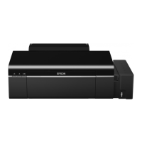
3. Remove the harness from the sensor (blue).
Figure4-21. Release Lever Position Sensor Removal
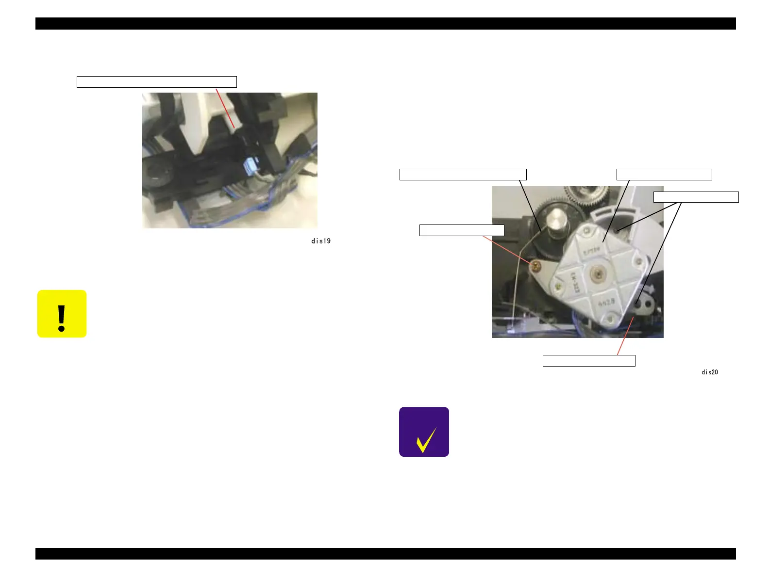
4.2.7.10 PF Motor Assembly Removal
1. Remove the printer mechanism. (See 4.2.3 "Printer Mechanism Removal".)
2. Remove the platen grounding wire from the platen.
3. Remove 1 screw (C.B.P., Tite, 3x10 F/ZN; Torque 0.59-0.78 N.M.) securing the PF
motor assembly to the right frame.
4. Remove 1 hook at the right frame securing the PF motor assembly to the right frame
and remove the PF motor assembly.
Figure4-22. PF Motor Assembly Removal
C A U T I O N
When installing the release lever position sensor, be sure to insert it
between the release lever and the right frame.
Release lever position sensor (blue)
C H E C K
P O I N T
When installing the PF motor assembly to the right frame, be careful
to align the position marking pin and motor bracket position marking
hole.
Platen grounding wire PF motor assembly
C.B.P., Tite, 3x10 F/ZN
Hook at the right frame
Position marking pin

 Loading...