LX-300+/1170 Revision C
Disassembly and Assembly Disassembly and Assembly 73
4.2 Disassembly and Assembly
This section explains the disassembly and assembly of Product Name. Unless otherwise
specified, assembly can be done in the reverse order of the disassembly procedure.
Anything that service person should pay attention to is described under “Check Point”. Any
adjustment required after assembly is described under “Adjustment”.
When you have to remove parts that are not described in this chapter, refer to the exploded
diagram on Appendix of this manual.
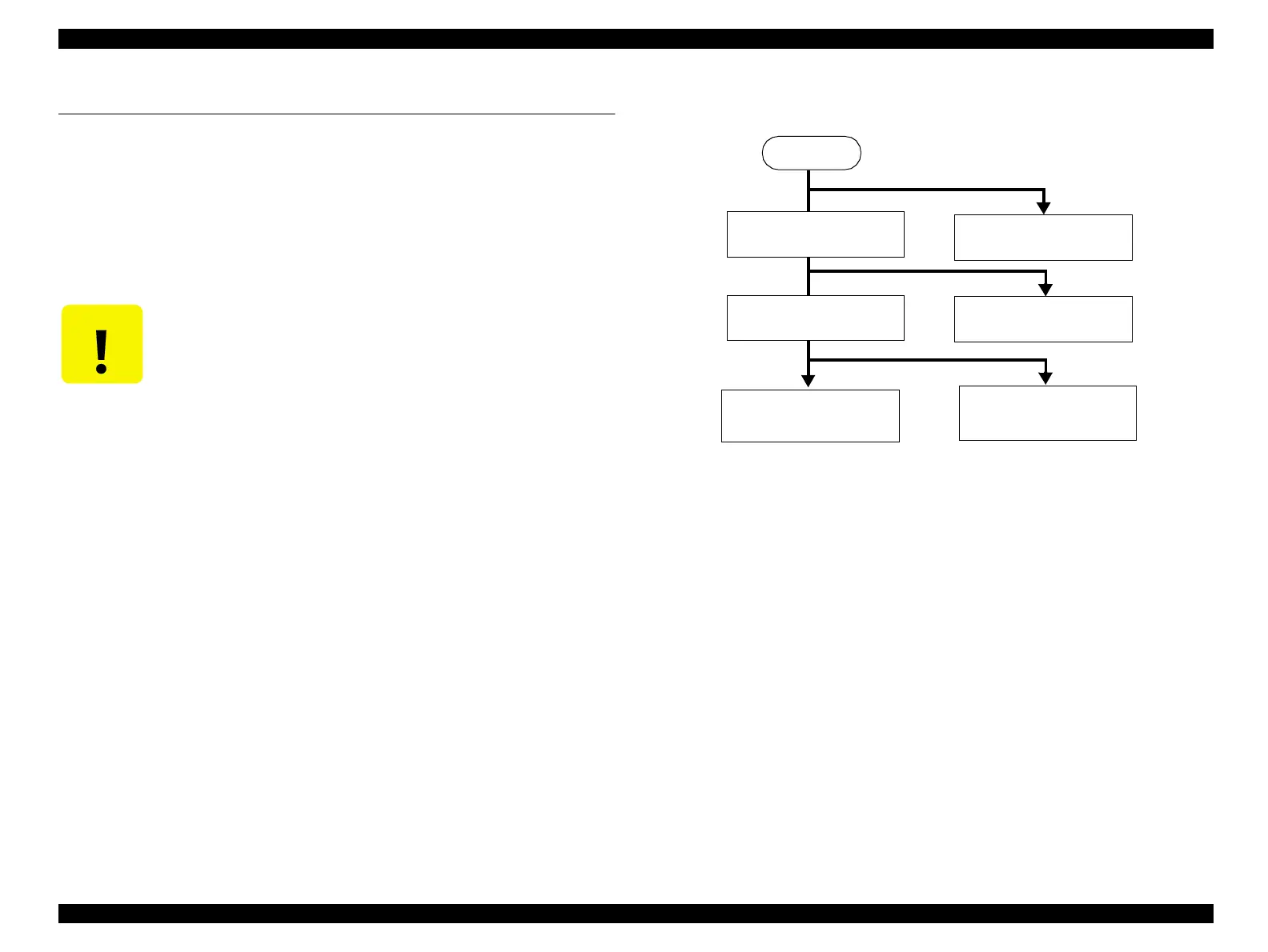
The figure below is the disassembly flowchart for main component.
Flowchart 4-1. Disassembly Flowchart (Main Component)
C A U T I O N
n Read 4.1.1 "Precautions" before start disassembling the printer.
n Remove ink ribbon and paper before disassembling the printer.
4.2.2 "Upper Housing
Removal"
4.2.1 "Printhead
Removal"
4.2.3 "Printer Mechanism
Removal"
4.2.4 "Board Assembly
and Panel Removal"
4.2.5 "C294MAIN/MAIN-
B Board Assembly
4.2.6 "C294 Power Supply
Board Assembly
START

 Loading...