LX-300+/1170 Revision C
Disassembly and Assembly Disassembly and Assembly 79
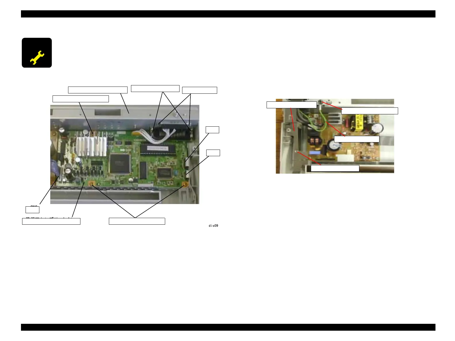
Figure4-7. C294MAIN Board Assembly Removal
4.2.6 C294 Power Supply Board Assembly Removal
1. Remove the upper housing. (See 4.2.2 "Upper Housing Removal".)
2. Remove the printer mechanism. (See 4.2.3 "Printer Mechanism Removal".)
3. LX-1170: Remove 1 screw(C.B.P., Tite, 3x10 F/ZN;Torque 0.78-0.98 N.M.)
and the left grounding plate.
4. LX-1170: Remove 1 screw (C.B(O), Screw, 4x8, F/ZN; Torque 0.98-1.18 N.M.)
and the grounding cable.
Figure 4-8. Ground Plate and Cable Removal (LX-1170)
5. Remove the power cable (CN1) connecting to the Power Supply board assembly.
Remove the power switch from the lower housing.
6. Remove the harness connecting the Power Supply board assembly to the main board
assembly. (CN8 of the main board assembly)
Press one edge of CN8 in order to remove or install the harness.
7. Remove 4 screws (C.B.P., Tite, 3x10 F/ZN; Torque 0.78-0.98 N.M.) securing the
Power Supply board assembly to the lower housing.
8. Remove the Power Supply board assembly.
A D J U S T M E N T
R E Q U I R E D
When the main board assembly is replaced, perform destination
setting and Bi-D adjustment.
Main Board Assembly
Hexagon Nut
Lower Shield Plate
C.P., Screw, 3x4 F/ZN
C.B.P., Tite, 3x10 F/ZN
CN8
CN13
CN12
C.B.P., Tite, 3x10 F/ZN
C.B(O), Screw, 4x8 F/ZN
Grounding Plate, Left
Grounding Cable
C.P., Screw, 3x4 F/ZN

 Loading...