118 Ion Operations Manual
{Channel} - In the patch display, all channels are displayed in numerical order. When multiple
devices are patched to the same channel, the channel number is only displayed in the first
row, additional devices are indicated with part extensions (example P2) on the next row of the
table.
Select the channel number using the control keypad or the direct selects.
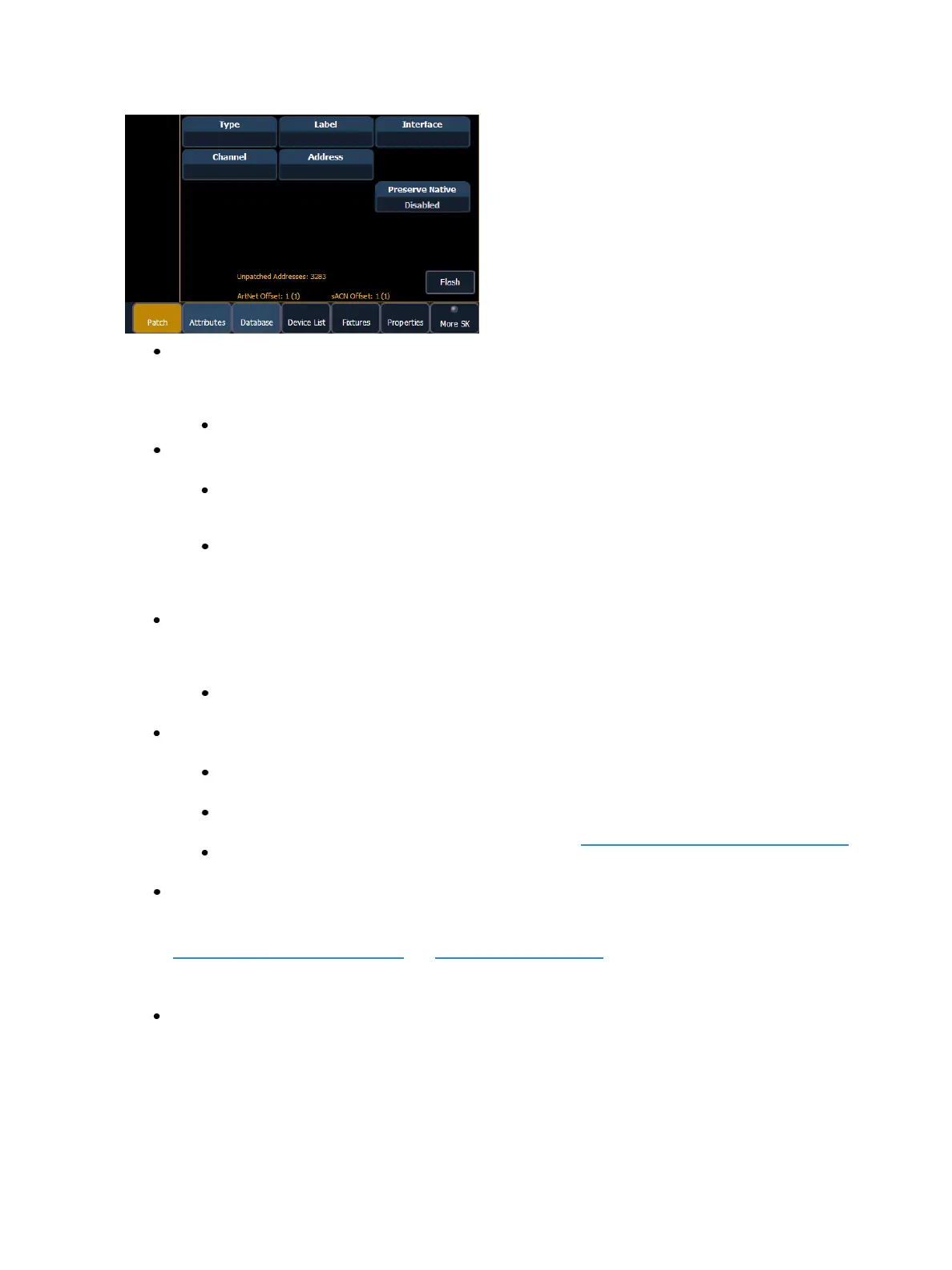
{Type} - Ion defaults to patching dimmers. To specify a specific device type for the selected
channel, press the {Type} button from the CIA.
The two columns on the left side of the CIA are pageable and show manufacturer
names. The four columns to the right of the manufacturer’s list are pageable devices
that are available from the selected manufacturer for patching.
Selecting a specific manufacturer repaints the display with all devices that are available
from that manufacturer. After you select a device, the fixture/ device type appears in
the command line, in the {Type} box in the CIA, and in the “Type” field for that channel
in the patch display.
{Label} - An optional user-defined label. You can use the [Label] key to display the virtual PC
keyboard on the CIA. Pressing {Label} or [Label], after a label has already been assigned, will dis-
play the label on the command line for editing purposes. Pressing [Label] [Label] will clear the
text.
[1] [At] [5] [Label] <S4 house right> [Enter] - patches channel 1 to output 5 and labels
channel it “S4 house right”.
{Address}- A required entry field for any device. You may use the either the [At] or
[Address/Patch] key instead of the {Address} button.
Use the keypad to define the starting address for the device (from 1 to 32,767,488) or a
port and offset value.You may enter a start address without defining an end address.
Ion will draw this information from the library data. If you wish to leave a larger output
gap than required by the library, use [Offset]. See Using {Offset} in Patch (on page106).
If you specify a start address that conflicts with other channels already patched, the
conflicting channels will be unpatched after a confirmation is provided by the user.
{Interface} - An optional field used to specify what network interfaces should be used for the
output. When the field is left blank, the default data output is used as selected in the {Net-
work} and {Local I/O} sections of the ECU. For more information about setting defaults see
Output Protocols (on page456)and Local I/O (on page466). The interface options available
are sACN, Net 2- EDMX, ArtNet, Avab UDP, and Local DMX, depending on what has been
enabled in the {Network} and {Local I/O} sections of the ECU for the desk. If an output option
is not enabled, it will not appear in the {Interface} list.
{Preserve Native} - When Preserve Blind Cue is enabled, and you make changes to patch, your
cues' real world levels (like pan degrees) will be converted so that the DMX output is preserved
instead of the degrees.This is primarily useful for fixture substitutions.