109
ELECTRICAL AND IGNITION
FLYWHEEL AND STATOR SERVICING
6
FLYWHEEL AND
STATOR SERVICING
IMPORTANT: Weak flywheel magnets can
cause low alternator output and affect outboard
performance. Weak flywheel magnets can also
cause low readings on ignition test equipment,
such as a peak-reading voltmeter, which might
cause unnecessary parts replacement.
An accurate test of alternator output can help
determine the flywheel’s condition. Refer to
CHARGING SYSTEM TESTS on p. 97.
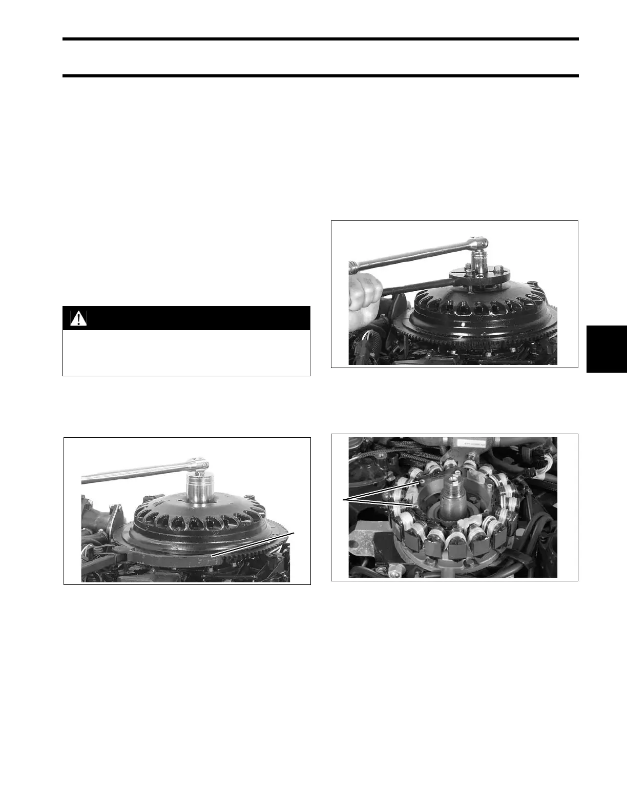
Flywheel Removal
Use Flywheel Holder, P/N 771311, or equivalent,
and a 1 7/16 in. socket to remove flywheel nut.
Discard flywheel nut.
Assemble the following components from Univer-
sal Puller Set, P/N 378103:
• Body, P/N 307636
• Screw, P/N 307637
• Handle, P/N 307638
• Three screws P/N 309492
• Three washers, P/N 307640
Apply Moly Lube grease to the threads of the
puller pressing screw, P/N 307637, and the center
hole of the crankshaft.
Place the puller on flywheel with body flat side up.
Attach the puller body with the three shoulder
screws and washers. Hold puller body with han-
dle, and tighten pressing screw until flywheel
releases. Turn the center screw and lift the fly-
wheel off of the crankshaft.
Stator Service
Remove six allen head screws to remove stator.
To install stator, position stator on cylinder block.
Apply Nut Lock to screw threads. Install screws
and tighten in crossing pattern to a torque of 24 to
36 in. lbs. (3 to 4 N·m).
WARNING
To prevent accidental starting while ser-
vicing, disconnect battery cables at the
battery.
1. Flywheel holder 000774
000772
1. Stator screws 006864