233
POWERHEAD
POWERHEAD ASSEMBLY
11
Install cylinder head with the thermostat toward
the top. Apply Triple-Guard grease to threads and
install the cylinder head screws. DO NOT use any
sealant on threads
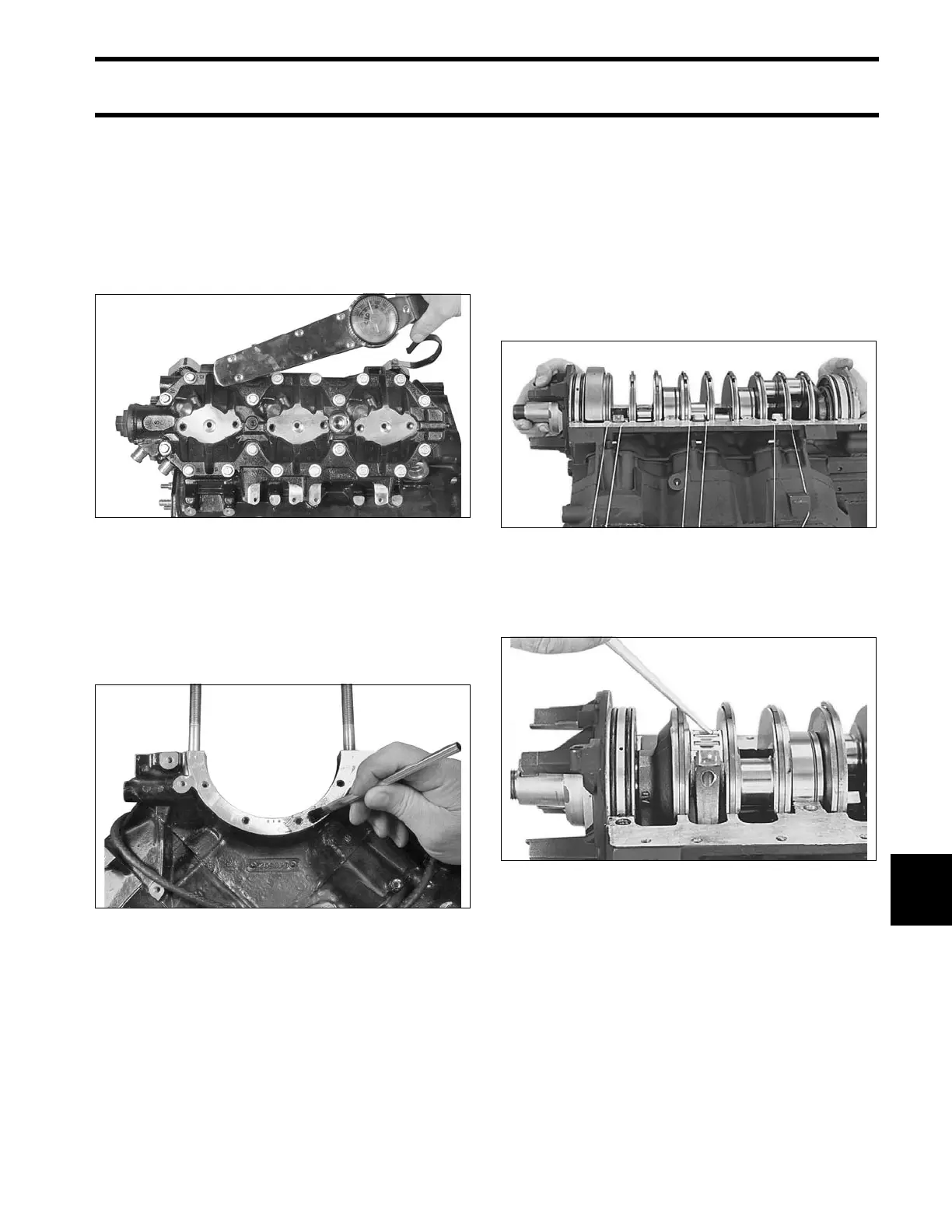
Following sequence stamped on cylinder head,
tighten all screws in stages to a torque of 17 to 19
ft. lbs. (23 to 26 N·m).
Crankshaft and Connecting
Rods
Lightly coat the cylinder block upper and lower
crankcase head flange surfaces with a thin layer
of Gel-Seal II.
Check that main bearing alignment dowel pins are
seated in the block.
Push all pistons to the top of cylinders. Remove
the numbered connecting rod caps and hold the
connecting rods to the outside with rubber bands.
Gently lower crankshaft into place.
• Turn all crankcase seal ring gaps to face up.
• Locate each main bearing on its dowel pin. A
mark placed on the bearing race opposite the
dowel pin hole will help in the alignment pro-
cess.
• Tap the crankshaft upward with a rawhide mallet
to seat crankshaft and lower crankcase head.
• Loosely secure upper and lower crankcase
heads with two screws.
Lubricate each crankpin and bearing assembly
with outboard lubricant. Slowly pull connecting rod
up to crankshaft and install bearing halves.
004133
004130
31828
31827