175
OILING SYSTEM
OILING SYSTEM TESTS
8
Cylinder Oil Pump Voltage Tests
The EMM controls the pump by providing ground
through pin 4 (blue/red wire) of the J1-A connector
and pin A (blue/red wire) of the oil pump connec-
tor.
Use an appropriate test probe and a digital multi-
meter calibrated to a scale that reads 12 V (DC).
Connect negative meter lead to ground.
Connect positive meter lead to pin A (blue/red
wire) of oil injection pump electrical connector.
Turn the key switch to the ON position. Observe
voltage at pin A.
• Voltage at pin A should be approximately 12 V.
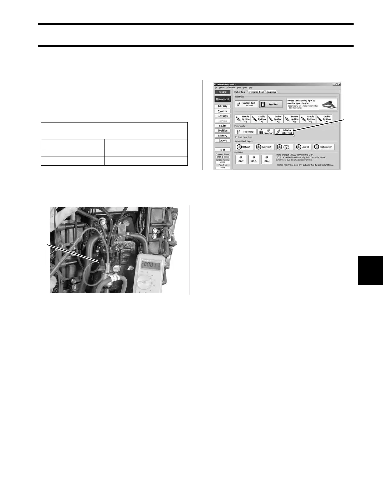
Use the Cylinder Oiler Test function of Evinrude
Diagnostic software Static Test screen to activate
the cylinder oil pump.
• Voltage at pin A should vary (drop), as the oil
pump cycles.
Check the control signal while the Oil Injector test
is running. Set the digital multimeter to the Hertz
(Hz) scale.
• Meter should read approximately 2 Hz.
Results:
• If voltage and control signal readings (Hz) at
pin A are within range, the EMM and wiring are
not at fault.
• If voltage at pin A is not within range, check volt-
age at pin B (red/yellow wire) of the oil pump
electrical connector.
Connect positive meter lead to pin B (red/yellow
wire) of oil injection pump electrical connector.
Observe voltage at pin B.
• The voltage at pin B should be approximately
12 V.
Start the engine. Observe voltage at pin B.
• The voltage at pin B should be approximately
12 V.
• If voltage at pin B is within range, refer to Cylin-
der Oil Pump Resistance Test on p. 176.
• No voltage reading at pin B, check continuity
between pin B of oil pump electrical connector
and pin 24 of EMM J1-B connector.
Acceptable Cylinder Oil Pump
Test Readings
Key switch ON approximately 12 VDC
Control signal approximately 2 Hz
Engine running approximately 12 VDC
1. Oil injection pump connector 008445
Static Test Screen
1. Cylinder oiler test
008468