342
TRIM AND TILT
ELECTRICAL CIRCUIT TESTS
ELECTRICAL CIRCUIT
TESTS
Relay Testing
When the trim-UP button is pressed, the UP relay
is energized and connects the blue trim motor
wire to the battery positive (+) terminal. The green
trim motor wire remains grounded. When the but-
ton is released, the blue trim motor wire returns to
a grounded position.
When the trim-DOWN button is pressed, the
DOWN relay is energized and connects the green
trim motor wire to the battery positive (+) terminal.
The blue motor wire remains grounded. When the
button is released, the green trim motor wire
returns to a grounded position.
Refer to TILT/TRIM RELAY TEST on p. 105 for
relay testing procedure.
Trim and Tilt Motor Current Draw
Tests
Careful analysis of the electric motor's current
draw and trim/tilt unit operating speed aids evalu-
ation of the electric motor and certain mechanical
components.
Use a battery rated at 360 CCA (50 Ah) or higher
that is in good condition and fully charged to per-
form this test.
IMPORTANT: Specifications are for static
hydraulic tests. DO NOT attempt to perform the
following tests while the boat is moving.
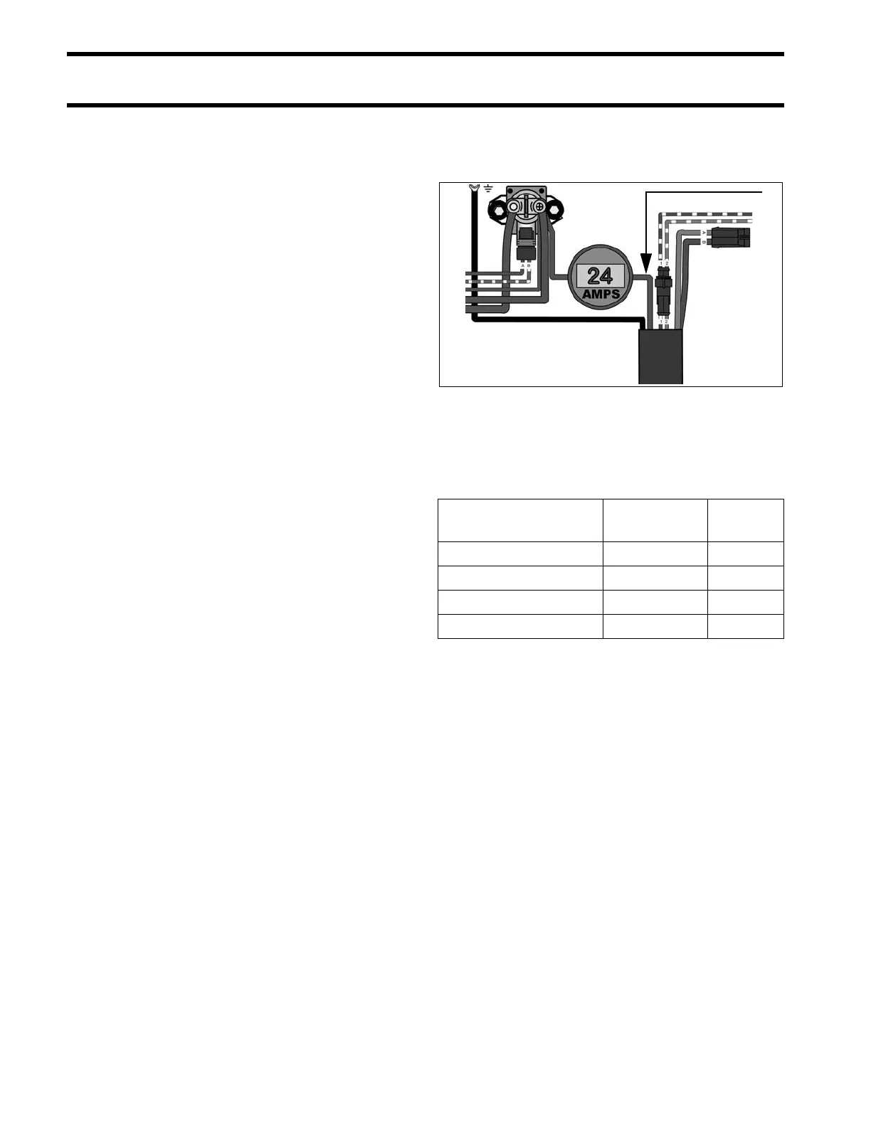
Connect a 0 to 100 A DC ammeter in series
between the battery side of the starter solenoid
and the red lead to the trim/tilt relay module.
Observe ammeter and a stopwatch while running
hydraulic unit through several complete cycles.
Compare test results to the values listed.
Test results include three basic possibilities:
A. Low current draw – Check for:
• Valves leaking
• Pump damaged
• O-rings leaking
• Manual release valve damaged
• Relief valve springs weak
• Check valves fouled or damaged
B. High current draw – Check for:
• Pump binding
• Motor binding
• Cylinder binding
• Valves sticking
1. Red lead 005441
Mode
Normal
Current Draw
Time in
Seconds
Trim-OUT (Trim range) 22 A 14
Tilt-UP Stall 80 A N/A
Trim-IN (Trim range) 16 A 7
Trim-IN Stall 35 to 45 A N/A