293
GEARCASE
SHIFT ROD ADJUSTMENT
13
On 25 in. and 30 in. models, place the appropriate
water tube spacer and grommet on the impeller
housing cover.
After water pump is assembled completely, rotate
driveshaft counter clockwise 1/4 turn to unlock
and release impeller and key from driveshaft.
Next, pull up on driveshaft and turn clockwise to
lock impeller to shaft. This process increases
pump efficiency by locking the impeller lower on
the driveshaft.
Before installing gearcase, shift rod
adjustment MUST be checked. Refer to SHIFT
ROD ADJUSTMENT on p. 293.
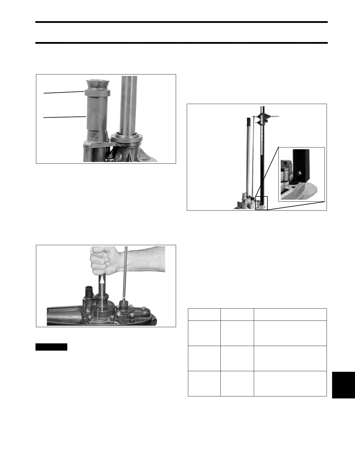
SHIFT ROD
ADJUSTMENT
Check the shift rod height from the shift rod hole to
the surface of the gearcase using Universal Shift
Rod Height Gauge, P/N 389997.
With the gearcase in NEUTRAL, rotate the shift
rod up or down as necessary for correct adjust-
ment. Once correct height is achieved, rotate rod
one half turn or less to direct offset forward.
IMPORTANT: The NEUTRAL detent is a two-
step design. Make sure the NEUTRAL detent ball
is in the center step before checking shift rod
height.
Shift Rod Heights
1. Spacer
2. Grommet
32728
007078
COA6166
Model Type Height
20 in. (L)
“L2”
“M2”
21 29/32 in.
(21.906 in./ 556 mm)
± 1/2 Half Turn
25 in. (X)
“L2”
“M2”
26 29/32 in.
(26.906 in./ 683 mm)
± 1/2 Turn
30 in. (Z) “M2”
31 29/32 in.
(31.906 in./ 810 mm)
± 1/2 Turn