237
POWERHEAD
POWERHEAD ASSEMBLY
11
Apply Permatex No. 2 to crankcase flange screws
where threaded hole is open to crankcase.Install
screws and tighten to a torque of 84 to 108 in. lbs.
(9.5 to 12 N·m).
Test that the crankshaft spins freely without bind-
ing.
Apply Nut Lock to the upper and lower crankcase
head screws. Install and tighten screws to a
torque of 96 to 120 in. lbs. (11 to 13.5 N·m).
IMPORTANT: After powerhead has been
assembled, allow at least two hours for Gel-Seal II
to cure before running outboard.
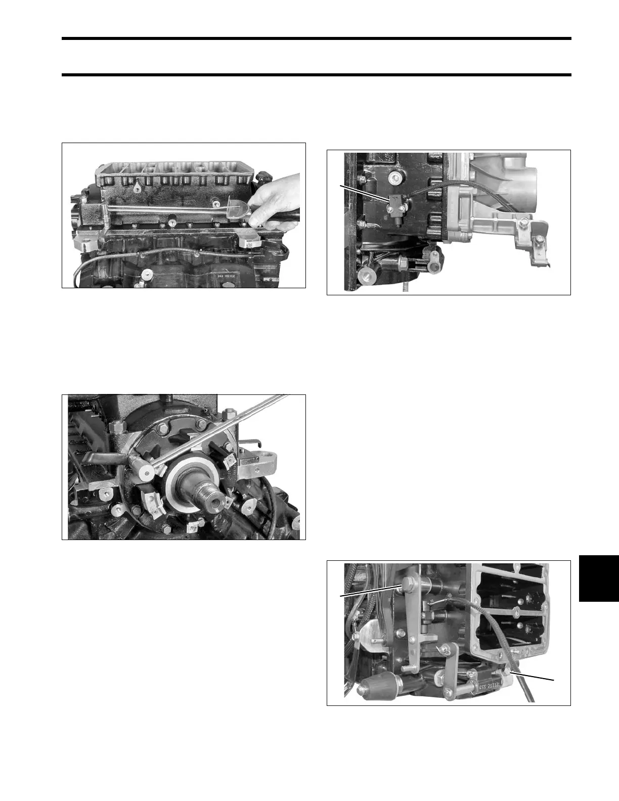
Shift Linkage Installation
Install Neutral/Shift Interrupt switch. Apply Nut
Lock to screw threads and tighten to a torque of 7
to 10 in. lbs. (0.8 to 1.1 N·m).
If removed, install cam on shift arm. Apply Ultra
Lock to screw threads and tighten to a torque of
60 to 84 in. lbs. (7 to 9.5 N·m).
Lubricate shift linkage bosses at the base of the
crankcase with Triple-Guard grease. Insert bush-
ings into bosses.
Apply Triple-Guard grease to the shaft of the shift
lever assembly. Guide shaft through bushings in
crankcase.
Install shift rod lever and tighten retaining screw
60 to 84 in. lbs. (7 to 9.5 N·m).
Apply Triple-Guard grease to shoulder of shift arm
screw and Nut Lock to threads. Install arm, screw,
and washer and tighten screw to a torque of 120
to 144 in. lbs. (13.5 to 16.5 N·m).
004138
004142
1. Neutral/Shift Interrupt switch 008451
1. Shoulder screw
2. Shift rod lever retaining screw
008455