187
COOLING SYSTEM
OPERATION
9
OPERATION
All models use a two-stage cooling system
design. The cooling system is dependent on water
pump pressure and controlled by thermostat and
pressure valve operation.
Restricted or inadequate water flow
through the outboard reduces cooling system
performance and may lead to severe power-
head damage.
Cylinder Block / Cylinder Head
Cooling
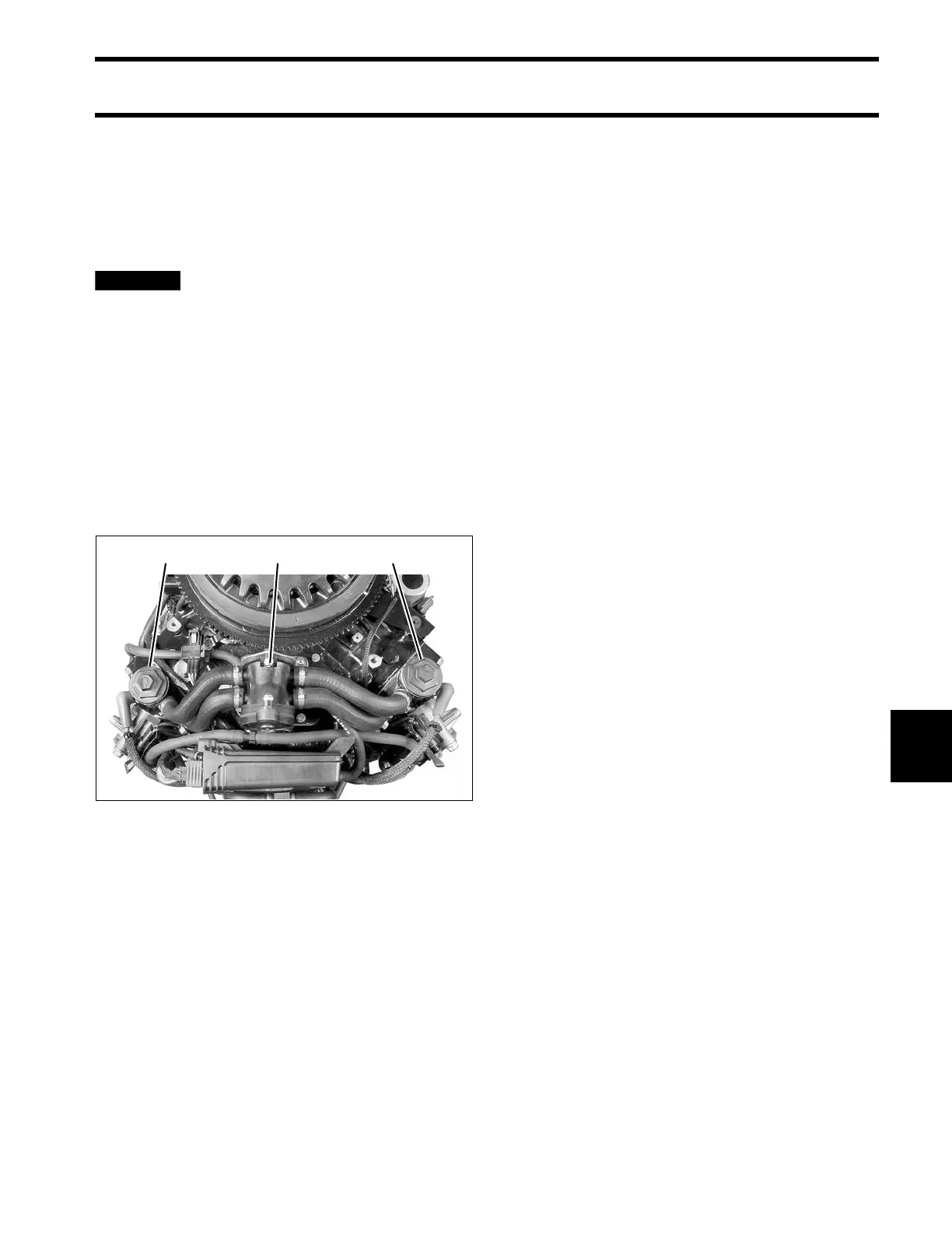
The flow of water through the cylinder block and
cylinder heads is controlled by two thermostats
and one external pressure valve. The pressure
valve is connected by hoses to the top of each cyl-
inder head.
The thermostats and pressure valve control the
flow of water entering the vertical water passages
of the cylinder heads.
At low speed, the pressure valve is against the
seat and the thermostats are closed. Warm water
from the cylinder block gradually migrates to the
thermostat pocket at the top of each cylinder
head.
The thermostat opens when the water tempera-
ture reaches approximately 143°F (62°C).
When the thermostat opens, water flows down
through the cylinder head to a passage in the cyl-
inder block. Water flows through the block to the
exhaust housing and then out of the outboard.
At higher speeds, water pressure opens the
pressure relief valve at approximately 1200 RPM.
Water flows through the valve and bypasses the
thermostats. Hoses route the water flow from the
pressure valve to the vertical water passages
below the thermostats. All water flows through the
cylinder heads to the outlet passages of the block
and then exits through the adapter housing.
This pressure controlled water outlet circuit pro-
vides a “high flow” discharge of water during high
speed operation.
This cooling system configuration provides “bal-
anced cooling” at higher RPM by using one pres-
sure valve to control the discharge of water
through both cylinder heads.
Additional Cooling
Two external water supply hoses direct water flow
into the exhaust (plenum) area of the cylinder
block. The water reduces exhaust runner temper-
atures and circulates through the cylinder block.
The base gasket limits water flow to the base of
the block and diverts water flow to the rear port
and rear starboard fittings of the adapter housing.
On 3.3 L models, a third external water hose
directs water flow from the exhaust housing of the
cylinder block to an exhaust passage at the
1. Thermostats
2. Pressure valve assembly
004269