347
TRIM AND TILT
TRIM AND TILT SERVICE
14
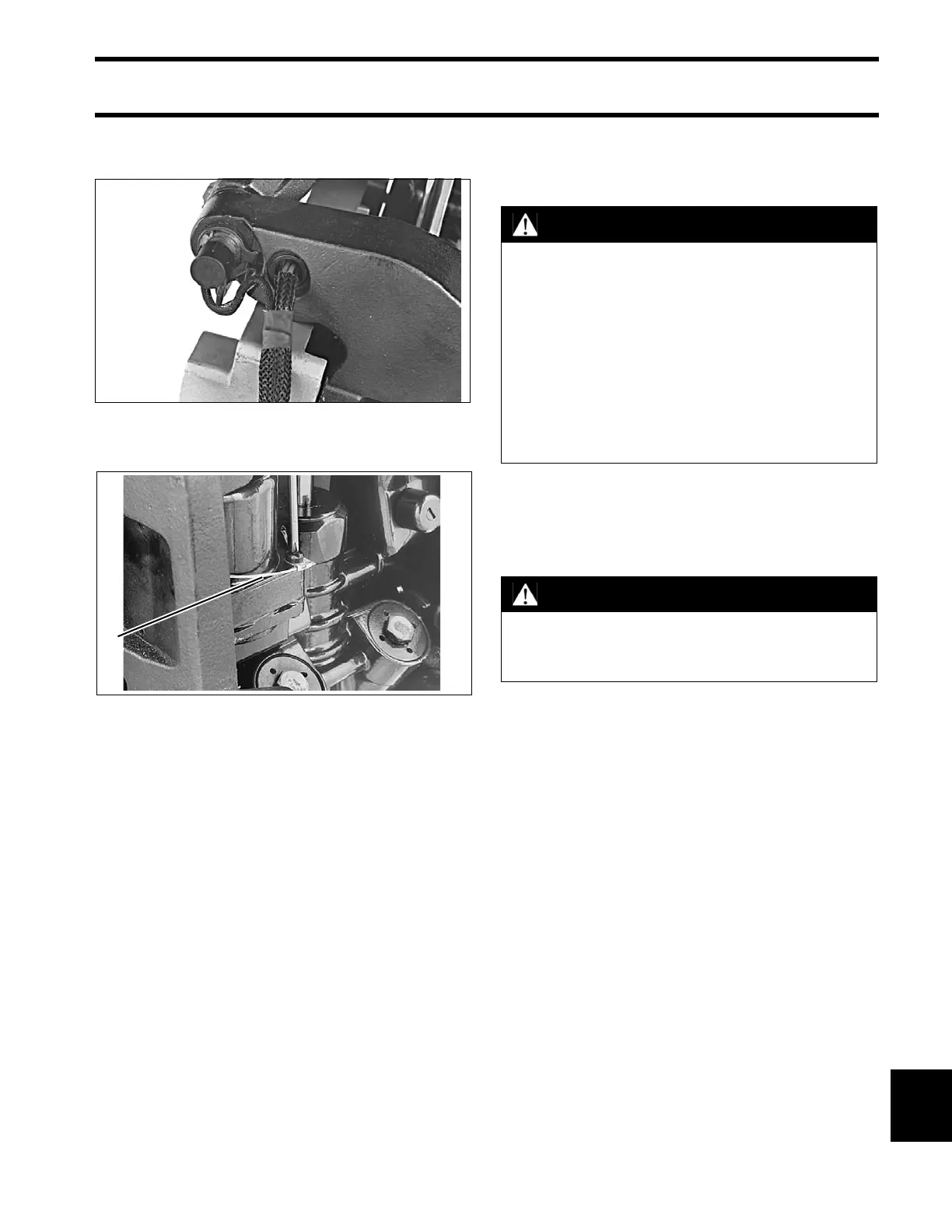
Place trim/tilt wires in braided tube and install
through hole in the stern bracket.
Attach the ground wire to the trim/tilt unit.
Release the tilt support and lower the outboard.
Tighten the manual release valve to a torque of 45
to 55 in. lbs. (5.1 to 6.2 N·m).
Install connector on trim/tilt cable and reconnect
trim connectors to engine wire harness.
TRIM AND TILT SERVICE
Disassembly
Thoroughly clean the unit before disassembling it.
Scrub all outside surfaces with a stiff brush and
hot, soapy water to prevent surface dirt from con-
taminating internal parts.
Always use a “lint free” shop cloth when handling
power trim/tilt components.
If painting the unit is required, paint it after it is
completely assembled. Painting of individual com-
ponents may cause flakes of paint to enter the
hydraulic passages during assembly. Tape the
trim/tilt piston rods before painting.
25079
1. Ground wire 25057
WARNING
Before removing the manual release valve,
operate the unit to the full UP position,
then run the unit down momentarily and
loosen the reservoir cap one full turn.
To avoid personal injury, always wear eye
protection when servicing the hydraulic
unit. Since there might be significant
residual pressure behind some compo-
nents, cover each component with a shop
cloth as you remove it.
CAUTION
Do not apply heat to the cylinder body or
cylinders. Excessive heat can cause high
pressure leaks or failure of parts.