219
POWERHEAD
POWERHEAD DISASSEMBLY
11
POWERHEAD
DISASSEMBLY
Systems Removal
To simplify reassembly and wiring installation, lay
out the various screws and clamps in the order of
their proper location.
Remove the electric starter. Refer to Starter
Removal on p. 115.
Remove fuel pump assemblies, fuel manifolds,
and filter. Refer to FUEL COMPONENT SERVIC-
ING on p. 143.
Remove EMM and electrical harness assembly.
Refer to EMM SERVICING on p. 70.
Remove stator. Refer to Stator Service on p. 109.
Remove oil pump, rear oil manifold, and oil circu-
lation hoses. Refer to OIL COMPONENT SER-
VICING on p. 178.
Remove ignition coils and fuel injectors. Refer to
Fuel Injector Service on p. 147.
IMPORTANT: Mark injectors for cylinder loca-
tion before removal. All injectors must be installed
in their original location. Improper injector installa-
tion can result in powerhead failure.
Remove throttle linkage. Refer to Throttle Link-
age Removal on p. 219.
Remove shift linkage. Refer to Shift Linkage
Removal on p. 219.
Remove the throttle body and reed plate assem-
blies. Refer to Intake Manifold Service on p. 151.
Remove pressure valve assembly. Refer to
PRESSURE RELIEF VALVE SERVICING on
p. 192.
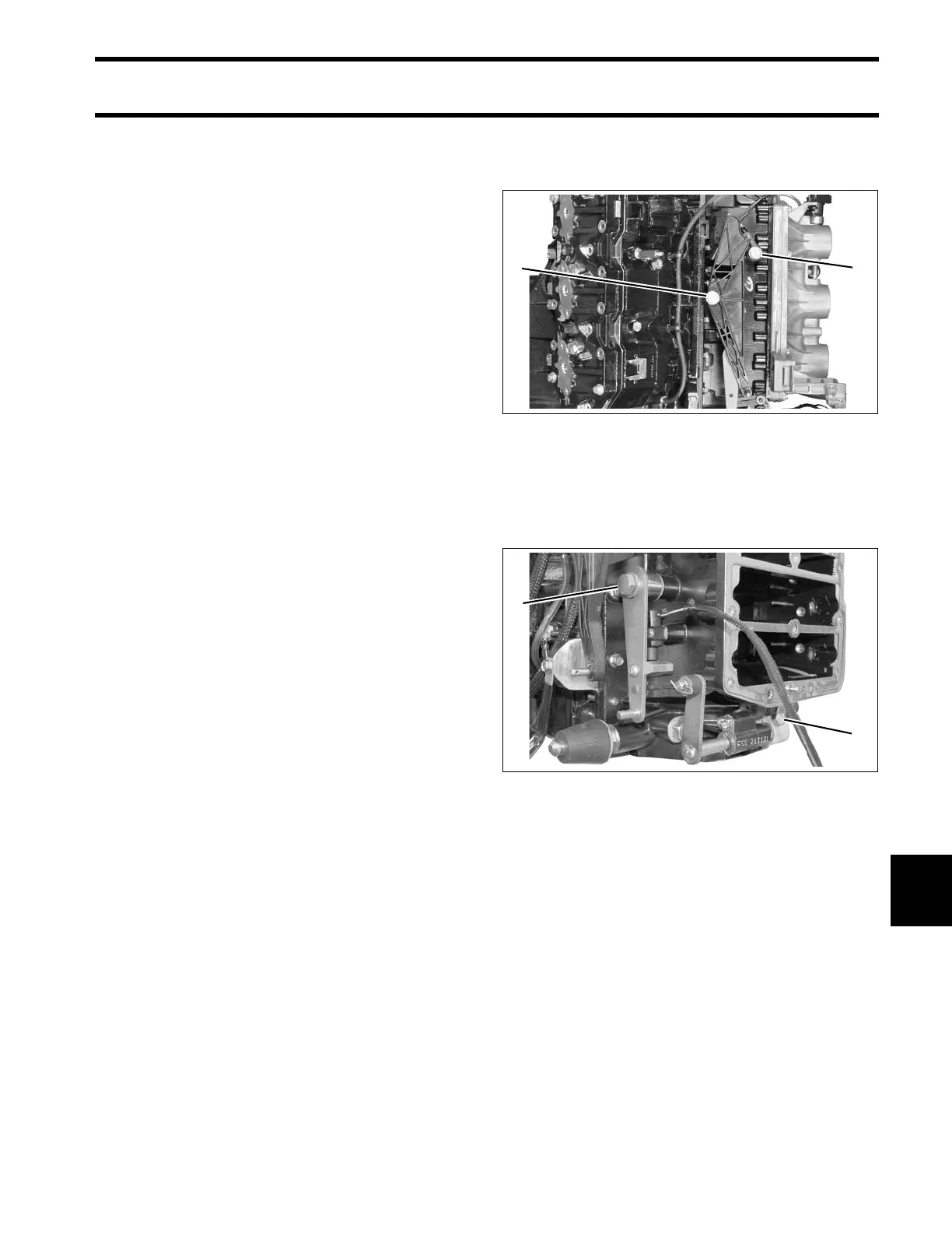
Throttle Linkage Removal
Remove throttle cam and throttle lever.
Shift Linkage Removal
Remove shoulder screw from shift arm and retain-
ing screw from shift rod lever
Slide entire shift linkage assembly from crank-
case.
Remove Neutral/Shift Interrupt Switch from cylin-
der block.
1. Throttle cam screw
2. Throttle lever screw
006866
1. Shift arm screw
2. Shift rod lever screw
008455