191
COOLING SYSTEM
TEMPERATURE SENDER SERVICING
9
TEMPERATURE SENDER
SERVICING
Removal
Loosen sensor and remove by hand. Use care to
avoid breaking threads.
Clean sensor threads, sensor, and sensor cavity.
Installation
Fill bottom of sensor cavity with 0.7 cc of Thermal
Joint Compound, P/N 322170. Sensor cavity
should be filled to 1 inch (25 mm) below the top
edge of the cavity.
Install sensor. DO NOT use gasket sealing com-
pound. SLOWLY tighten temperature sensor to a
torque of 50 to 70 in. lbs. (5.6 to 8.0 N·m).
Wait 10 minutes for trapped air to bleed from cav-
ity. Thermal compound may seep past threads.
Retighten sensor.
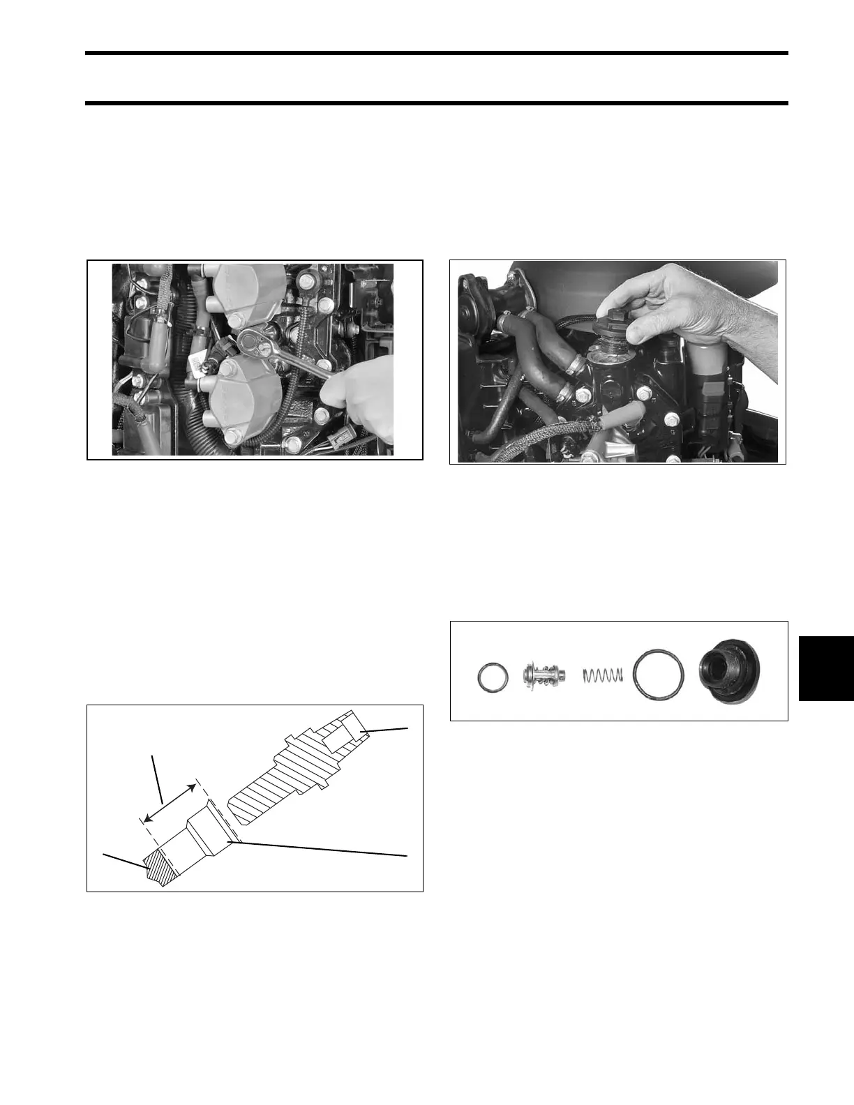
THERMOSTAT
SERVICING
Disassembly
Remove the thermostat cover and O-ring from cyl-
inder head.
Remove spring, thermostat, and gasket.
Inspection
Inspect all parts for cracks, heat damage, or signs
of corrosion. Replace damaged parts. Clean
debris from housing and parts.
Assembly
Assembly is the reverse of disassembly. Pay
close attention when performing the following
additional tasks.
Coat threads of each cylinder head thermostat
cover with Gasket Sealing Compound. Install and
tighten the cover to a torque of 120 to 144 in. lbs.
(13.5 to 16.5 N·m).
007209
1. Temperature sensor
2. Sensor cavity
3. Thermal joint compound
007049
004338
000757