150
FUEL SYSTEM
FUEL COMPONENT SERVICING
Install Injector
The following items and their mating surfaces
must be cleaned before reassembly:
• Injector
• Cylinder head
• Adapter
• Screws
• Threaded areas
Place injector and insulator in the proper cylinder
location.
IMPORTANT: Be careful not to pinch any wiring
or hoses during assembly.
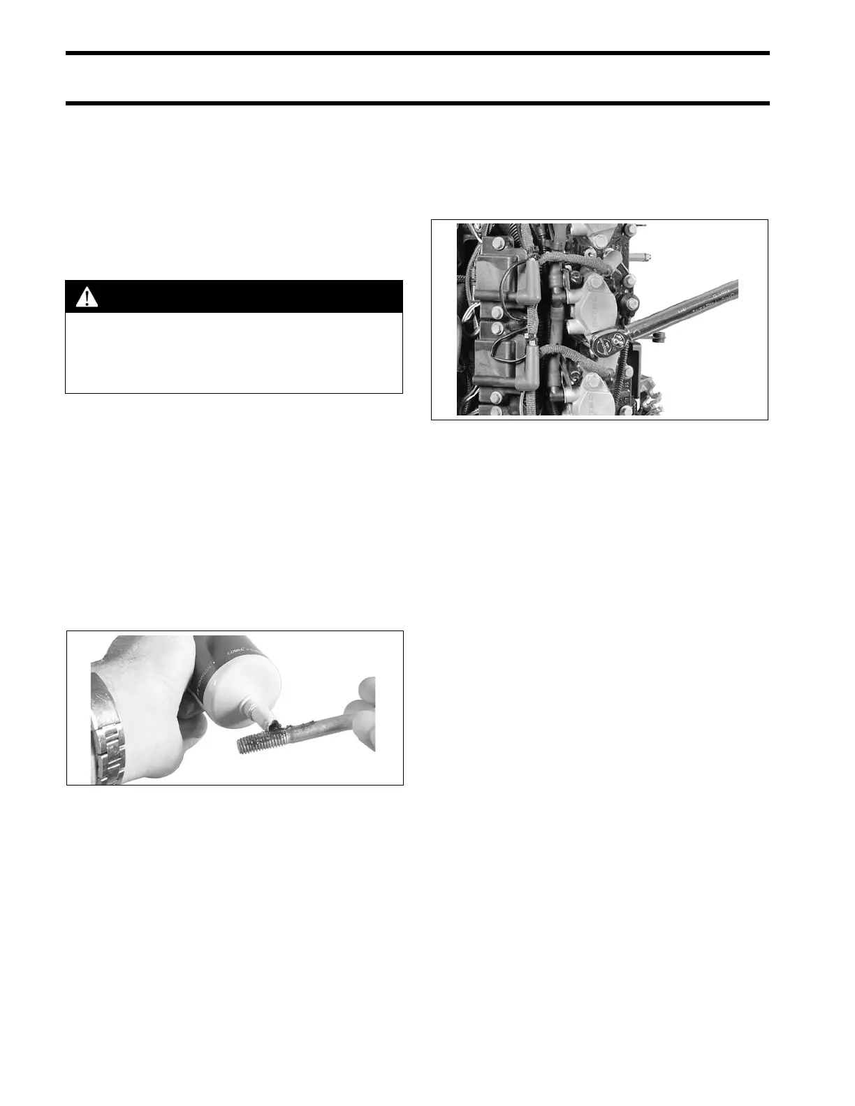
Lubricate mounting screw threads and under the
head of the screw with a light coat of Triple-Guard
grease. Install washers (one per screw) on injec-
tor retaining screws. Install screws and washers
through mounting flange of injector and into cylin-
der head.
Tighten screws in stages, starting with the lower
screw.
• First torque is 5 ft. lbs. (7 N·m)
• Second torque is 10 ft. lbs. (14 N·m)
• Final torque is 24 to 26 ft. lbs. (33 to 35 N·m).
Reconnect fuel injector electrical connectors.
Install fuel manifolds. Refer to Fuel Manifold Ser-
vice on p. 146.
CAUTION
All injector components must be clean to
ensure correct torque tightening specifi-
cations. To prevent fuel leakage, carefully
follow these installation instructions.
002316
Tighten Screws in Stages 007210