19
ROUTINE SERVICE
OUTBOARD RIGGING CONNECTIONS
2
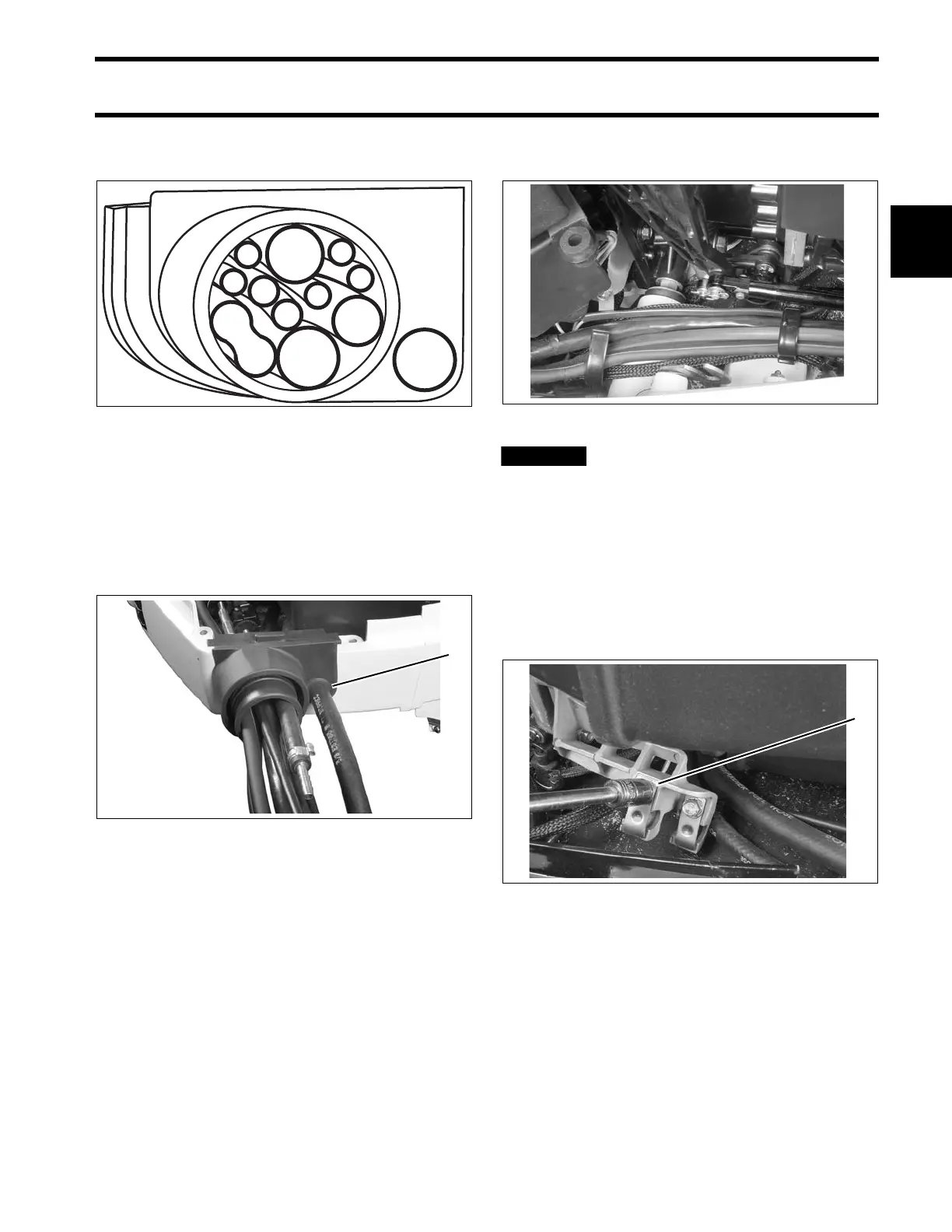
Refer to the following diagram to ensure proper
positioning of rigging components in grommet.
The main wiring harness, battery cables, oil tank
sending unit harness, and any ICON or I-Com-
mand network cables should be routed along the
same path to the starboard side of the powerhead.
Secure all cables with clamps.
After installation, make sure there
is enough clearance for all cables to avoid
binding or chafing through all engine steering
and tilting angles.
Control Cable Installation
Refer to Control Cable Identification on p. 17.
Remove control cable trunnion covers and cable
attachment hardware.
1. Fuel supply hose
2. Fuel supply hose--alternate location
3. Oil supply hose
4. Oil tank sending unit harness
5. Battery cables
6. Main wire harness (MWS)
7. Shift cable
8. Throttle cable
9. Accessory charge wires
10. I-Command harness
11. Water pressure hose
12. Speedometer hose
000095
1. Alternate fuel hose location 003971
003974
1. Trunnion covers 005037