289
GEARCASE
GEARCASE REMOVAL AND INSTALLATION
13
IMPORTANT: New gearcase screws are treated
with a thread-locking material. Apply Triple-Guard
grease to threads to ensure that the correct
clamping force is achieved when tightening—If a
previously installed screw is re-used, use a wire
brush to remove any old thread-locking material or
corrosion and lubricate threads with Triple-Guard
grease.
Install screws and washers and tighten to a torque
of:
• 3/8 in. screws – 26 to 28 ft. lbs. (35 to 38 N·m)
• 7/16 in. screw – 45 to 50 ft. lbs. (61 to 68 N·m)
Apply Triple-Guard grease to threads of the trim
tab screw. Install gasket on “M”-type gearcases.
Install and align the trim tab (cover on “L”-type)
with the index marks noted prior to disassembly.
Tighten the trim tab screw to a torque of 35 to 40
ft. lbs. (47 to 54 N·m). For adjustment, refer to
Trim Tab Adjustment on p. 30.
Standard rotation and counter rota-
tion trim tabs must not be interchanged. This
would result in inadequate cooling water sup-
ply to the propeller hub.
Place the shift rod in the shift rod lever. Install the
retaining pin and washer. Tighten pin to a torque
of 60 to 84 in. lbs. (7 to 9.5 N·m).
IMPORTANT: During break-in period of a reas-
sembled gearcase, change the gearcase lubricant
between 10 to 20 hours of operation.
1. Alignment bolt
2. 3/8-16 x 1.75 in. screw
005403
1. 3/8-16 x 3.5 in. screw
2. 7/16-14 x 3.5 in. screw
006869
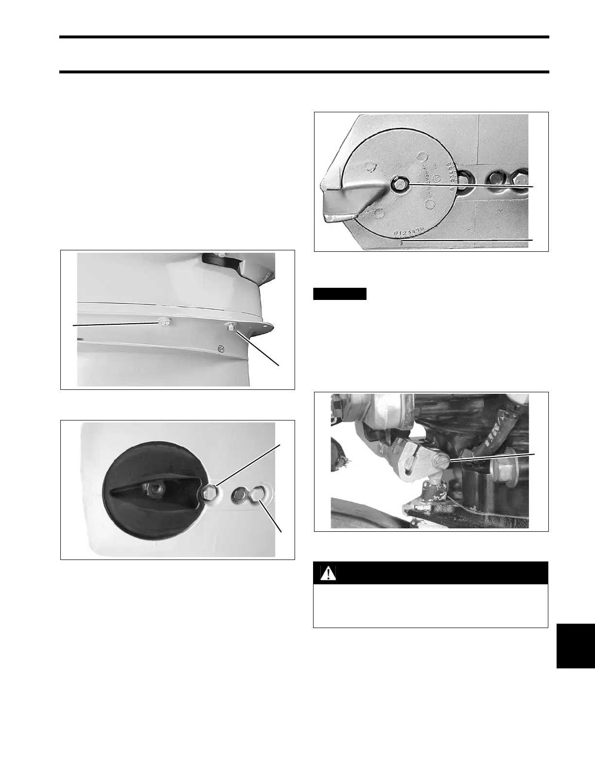
1. Trim tab screw
2. Index mark
COA3663
1. Shift rod screw 004241
WARNING
To prevent loss of operator control, check
for proper shifting operation and adjust, if
necessary.