IN1608 xi Scaling Presentation Switcher • Operation 45
AUDIO
INPUTS OVER DTP
RS-232
IR
Tx Rx Tx RxG
POWER
12V
0.7A MAX
SIG LINK
DTP OUT
DTP HDMI 4K 230 Tx
x
100-240V ~ 1.5 A MAX
1
2
CONFIGURABLE
HDMI
HDMI
5
6
7
8
1C
RS-232 IR
RS-232 IR
Tx Rx Tx RxG
Tx Rx Tx RxG
Tx Rx Tx RxG
HDMI
1A
1B
3
4
INPUTS
OUTPUTS
Tx Rx
RS-232
G
2x25W(8Ω)/2x50W(4Ω)
RESET
AUDIO INPUTS
OUTPUTS
REMOTE
LL1
RR
L2
R
L
3
R
CLASS 2 WIRING
L4
R
L5
R
+48V
+48V
12
LR
VARIABLE
IN1608 xi IPCP SA
2
MIC/LINE
L6
R
SIG LINK
DTP IN
SIG LINK
DTP IN
SIG LINK
DTP OUT
50/60 Hz
RS-232 IR
OVER DTP
OVER DTP
AMPLIFIED OUTPUT
DTP
HDBT
Tx Rx
RTSCTS
G
Tx Rx GTxRxG
LAN
AV LAN 2
AV LAN 3
AV LAN 1
R
1234G
DIGITAL I/OCOM 3COM 2COM 1
SSGG
1
1
2
2
C 34C
-S G+S+V
PWR OUT = 6W
IR/SERIAL eBUSRELAYS
RS-232
RS-232
1608 xi IPCP SA
RS-232
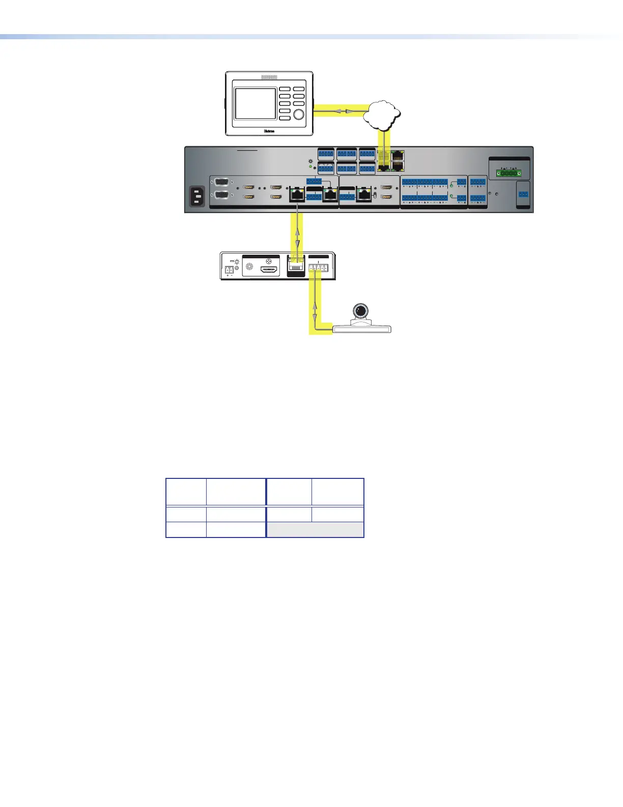
Insertion
Network
Figure 34. Typical Ethernet to RS-232 Insertion to an Input Endpoint
Port number
For Ethernet to RS-232 insertion, the insertion port number must be stated from a specific
starting point. This number is entered as the Telnet port number when you establish
communication with the insertion port.
For the purposes of this discussion, consider the Ethernet insertion ports as serial (RS-232)
ports. The rear panel Over DTP RS-232 port, both input ports, and the output serial port on
the scaler are numbered sequentially (see the table below for the port default numbers).
Input
Port
Insertion
Port
Output
Port
Insertion
Port
7 2001 1C 2003
8 2002
Changing the starting point
By default the starting port number is 2001. You can change the starting port number by
any of the following methods:
• Using the Product Configuration Software (see IN1606 and IN1608 Series PCS Help file)
• Using SIS commands (see the Set UART starting point SIS command on page 76)
• Using the internal web page (see Insertion port on page 123)

 Loading...