Ø
New device from clipboard: allow you to copy
the devices data from a customer and after paste
them in another customer.
Ø Upload from board: to download the program-
ming (via serial link) to the connected control panel.
Ø Download to board: to upload all the program-
ming (via serial link) of the connected control panel.
Ø Print a text file; in this case, the list of devices fit-
ted within the control panel loop.
Ø Device's details: a further window allow you to see the
points and the Outputs where the devices is enabled.
Ø
Select: allow you to select all present devices.
+
If different devices have common programming pa
-
rameters, you can use the multiple selection of the
devices and assign the same parameters.
+
You can see (view) the list of devices included
in List or Grid, put the check.
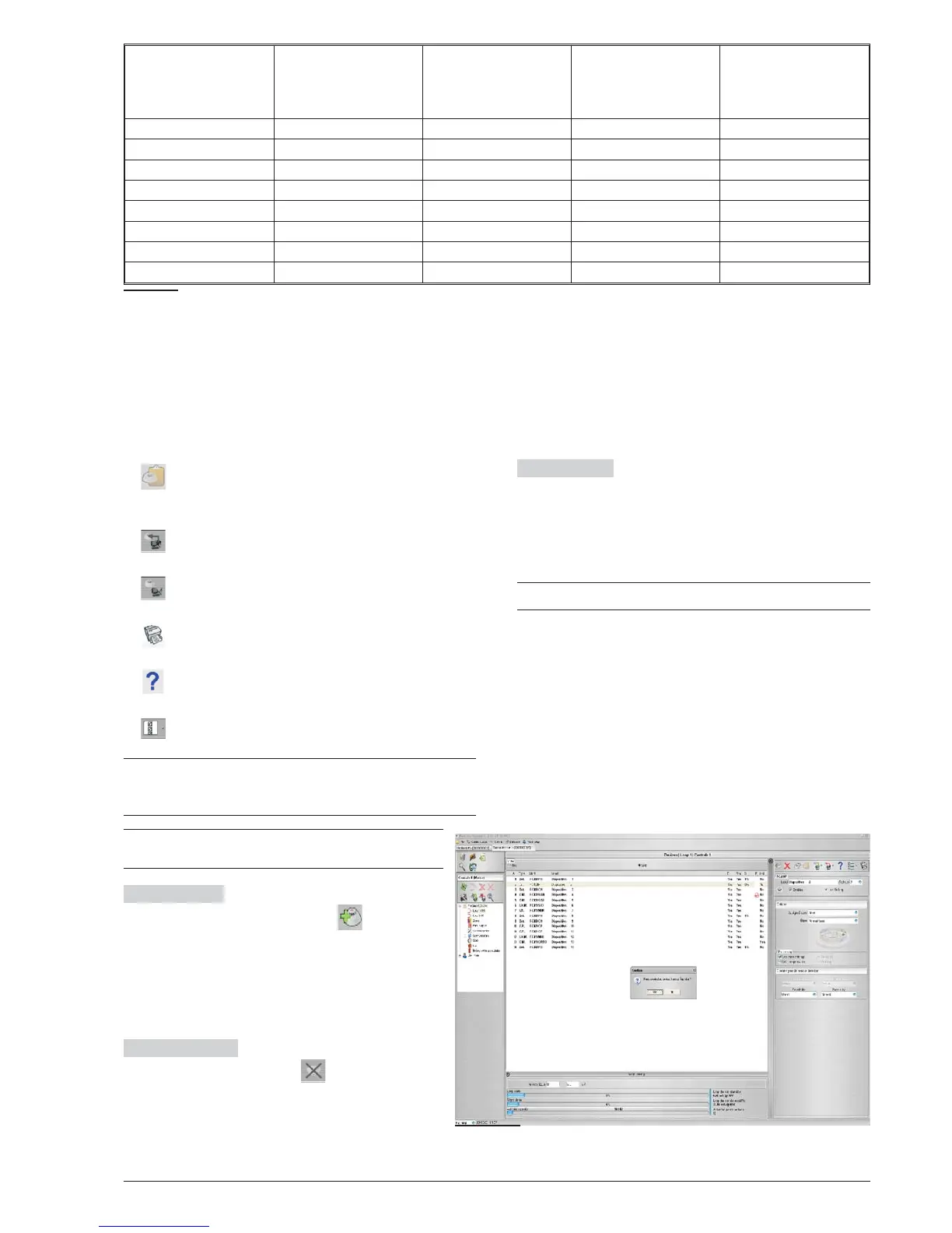
Select devices
Click-on Panel 1, select Loop 1
or Loop 2, click on "new device" , the window
in Figure 26 will shown:
select the programming devices, enter a valid ad
-
dress, and after click-on
3 OK to put the devices
in configuration. For others devices, repeat the
same procedure.
Remove devices Select the device, therefore
click-on "Remove device" , and confirm the
choose
3 OK.
Loop Loading At the end of "Device programming
window", Figure 26, there is a Loop Loading section.
Here, the "Loop drain" and the "Signal drain" will be
shown . On the right, the "Loop drain in stand by", the
"Loop drain in alarm (50%)", and the "battery needed"
will be shown.
+
The remote LEDs may be entered in the calculation
The percentage shown in the "Loop drain in alarm
(50%)" is the programmed value in "Battery calculation"
an option of Configuration menu (see dedicated para-
graph).
n
Parameters detectors programming
Click-on device in configuration, the relative program
-
ming window will shown (every device has the dedica
-
ted programming window).
For the detectors (see figure 26);
in the Multiple sources section:
32 Addressable Fire Control Panels FC500
Detector
Class
Typical application
Temperature
°C
Max. Application
Temperature
°C
Min.Static
Response
Temperature
°C
Max.Static
Response
Temperature
°C
A1 25 50 54 65
A2 25 50 54 70
B 40656985
C 558084100
D 709599115
E 85 110 114 130
F 100 125 129 145
G 115 140 144 160
Table 6 Detector classification Temperature - Detector shall conform to one or more of the following classes: A1,
A2, B, C, D, E, F o G . Manufacturers may optionally give additional information concerning the type of response exhi
-
bited by the detector, by adding the suffix S or R to the above classes.
Detectors, with a suffix S to their class, do not respond below the minimun static response temperature, even at high
rates of rise of air temperature.
Detectors, with a suffix R to their class, incorporate a rate of rise characteristic, which meets the response time requi
-
rements for high rates of rise of air temperature even when starting at air temperature substantially below the typical
application temperature (EN54-5:2000).
Figure 27 Detector Disablement confirmation window.