Prealarm duration: an input device programmed with
Prealarm time will generate ALARM status when the
prealarm time elapses.
Prealarm status is signalled by: an audible signal emit
-
ted by the control panel;
Ø
blinking on the PREALARM LED;
Ø
the message on the display;
Ø
activation of outputs with programmed Prealarms.
Silence duration: when the control panel is in Night
Mode the Silence delay is the maximum silence time of
the Outputs.
Reset: program the Reset time ( min Time: 2 sec; max
Time: reset AUX-RES Output, see AUX-RES terminal).
Password section: the Password section will allow
you to change the Installer and User codes. Codes
with 1 to 5 digits (0 through 9).
Installer code allows to manage the 3 access Levels of
control panel: L1(View), L2 (User), L3 (Installer).
The default installer code is 00000: every digit will be
hidden by *(star) symbol.
User code allows to manage 2 access Levels of con
-
trol panel: L1(View) and L2 (User).
The default User code is 11111: every digit will be hid
-
den by *(star) symbol.
Loop section: in this section select the required Loop
configuration: a 2 wire connection or a 4 wire connection.
Language section: select the avalaible language the
display of Control panel and Repeater will use. It is pos-
sible to upload others languages from the software.
Day-Night mode section: select the DAY or NIGHT
mode, or a tick [
3]onAutomatic enter the time (hour
and minutes) when the day-night mode changes
.
+
When you set the time to transition from DAY to
NIGHT mode make sure that the time is less than
the hour to be set for switching between Day and
Night mode.
FC500REP: a tick [
3] enables the Repeater faults si
-
gnalling.
Network: a tick [
3]onEnable Network enables the
Slave control panel on the Network, and a a tick [
3]on
Network Commands enables the Control pa
-
nels that have the same tick [
3] to do the com
-
mands (Reset, Silence, Investigate) programmed
in other Network control panels.
Allow silence buzzer: If this option is enabled it is
possible to silence a device that is activated by
every part of the network.
In the section Network (Figure 30): the options
Linked slaves, Linked repeaters and MFI allow
you to enable Slave control panels, Repeaters and
FC500 MFI modules. For FC500MFI module see
the programming from the panel at pag. 50.
NAC Fire: a tick [
3] indicates if the NAC FIRE is
disabled.
Conventional zone: a tick [
3] indicates if Con
-
venzional zone is disabled.
+
The Slave control panel address can be inserted
from the User interface of the same control panel;
the Repeater address can be inserted from the pa
-
nel of the same Repeater (see Programming from
the panel).
The FC500PSTN interface and the FC500IP module
are enabled in the Communicators section. A single
click means the interface will be present but not active,
while a double-click enables the FC500PSTN or
FC500IP module. You may also choose whether to
enable both alarm and breakdown events or just one of
the two. The delay times corresponding to the zone, po
-
int and control panel alarms are set in the Alarm Ti
-
mers section.
Languages:in the Languages section, you have the
option to change the system language from those avai
-
lable. Once in the Available Languages have loaded
the two languages among those available, press the
button to overwrite one of the two languages in the
panel memory. As soon as the download of the new lan
-
guage will be completed, the plant will start to use it, and
update their device, if necessary. To change the lan
-
guage currently active on the system, use the button
in the section Change system Language.
Advanced
In the Advanced section you have the
possibility to set the thresholds for gas detection device
FC410DDM, press the icon .
PSTN interface
For an explanation of the various commands and pro-
gramming procedures, please refer to the dedicated
FC500PSTN manual.
36 Addressable Fire Control Panels FC500
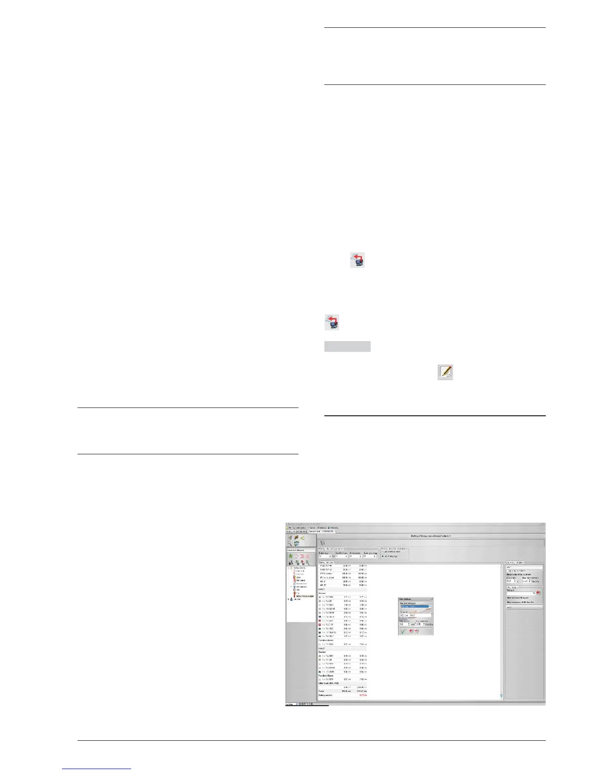
Figure 31 Battery calculation window