see the customized Manaul), the relative programming
window will shown.
+
Click-on yellow bar to open or close the relative
section of parameters programming
The description is as per the same Input/Output Modu
-
les section. Compared to this paragraphs, there is a
further field "Label" where a description of Input/Output
Module will be inserted.
n
Manual Call Point programming parameters
Click-on a Manual Call Point (FC420CP) the relative
programming will shown as per the following description.
Manual call point section: come per i Sensori
assigned zones: each Manual Call Point can be asso
-
ciated with 1 of the avalaible software zones (64 for
FC510, 128 for FC520 control panel).
Ø
Led blinking: if this option is enabled, the Manual Call
Point LED will blink every Loop scanning.
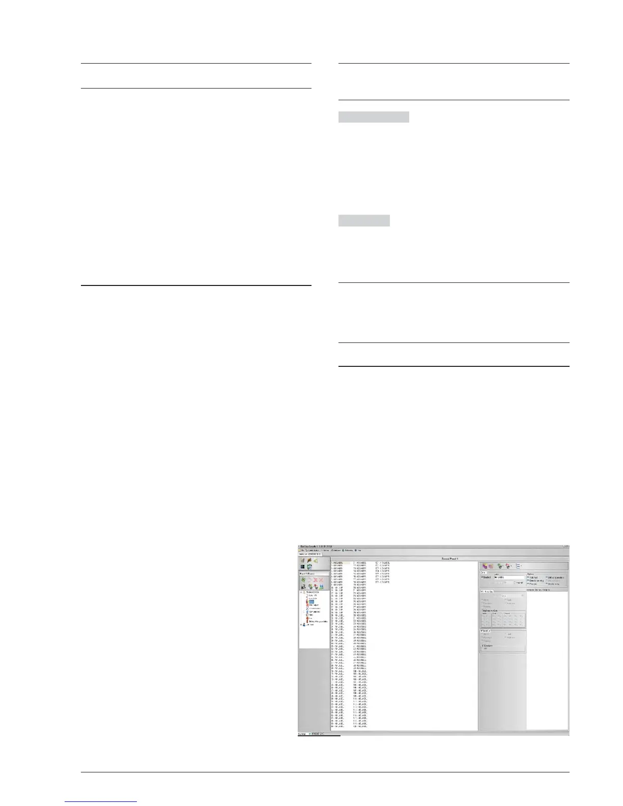
Zones programming
The Zone option from the pull-down menu will allow you to
access the software-zone parameters (see Figure 28).
The software zones parameters will be applied automati
-
cally to all the devices associated with the zone concerned.
First section (see Figure 28) on the right;
Ø Enable: a tick [
3] indicates if the zone is enable.
Ø Label: this is for the editable device-label (up to 20
characters). The system will use the label as the
zone identifier.
Ø Preallarm Duration: an input device programmed with
Prealarm time will generate ALARM status when the
prealarm time elapses. (see parameters programming
detector).
Select the Prealarm time;
the default prealarm time is 1 minute.
Enter values of 0.00 through 10.00 minutes with
steps of 5 seconds.
Options section: many parameters can be program
-
med in this section.
Ø
Walk test: if this option is enabled, the zones in
alarm status will activate the programmed
Outputs with Walk test, while the control panel
will not generate an alarm.
Ø
Detector Warning: if this option is enabled the
control panel will activate a WARNING signal.
N.B. To activate the Warning option for a Mo
-
dule, tick the corresponding box on the Module
programming screen.
Ø
Prealarm: if this option is enabled, the control
panel will activate the ALARM delay.
Ø
Drift Compensation: see the same option in
"Parameters detectors Programming";
Ø
Double Knock: if this option is enabled and
the zone is in Prealarm status, when an other
devices (other address) associated to this
zone will be activated, the zone will immedia
-
tely generate an Alarm status.
Ø
Smoke delay: for each zone, you can program
the delayed activation of the smoke detectors.
The procedure can be triggered via software or panel
(see page 47)
+
Click on Zone number to see which devices are ena
-
bled on that zone. Moreover a double ckick on asso
-
ciated device to zone, opens a Details Device window.
PSTN interface The PSTN interface section is activa
-
ted, after the FC500PSTN Telecom module has been
enabled on the General Options screen (Figure 30). In
this section, each zone may be associated with one or
more voice messages linked to an Alarm, Pre-alarm,
Start-up, Breakdown or Walk Test event; these may be
sent to a maximum of 32 telephone numbers (please re
-
fer to the specific FC500PSTN manual).
IP interface
The IP interface section is active after the
module FC500IP has been enabled in the General
Options page (Figure 30). Each zone can be associated
with an event of alarm, Prealarm, Warning, Fault and
Test (see the dedicated manual of FC500IP module).
+
If the procedure to "restore the factory defaults" of
control panel will be executed (see Icon descrip
-
tion), even the FC500PSTN Interface is restored to
the factory defaults, while the programming data of
FC500IP are not affected.
Outputs Programming
The Outputs option from the pull-down menu will allow
you to access the outputs parameters. The relative pro-
gramming will shown as per the following description
(see Figure 29).
n NAC1, NAC2 and NAC3 Outputs
Supervised/Silenceable/Bypassable (Disabled) Alarm
Outputs.
Output ACTIVE: positive pull-up to 27.6 V on the [+] ter
-
minal; negative pull-down to 0 V on the [–] terminal.
Click-on a Output, the relative programming window will
shown:
In the first sezione:
34 Addressable Fire Control Panels FC500
Figure 28 Zones Programming window.