+
The NAC1, NAC2 and NAC3 Bell Outputs are Pro
-
grammable, Supervised, Silenceable, Bypassable
(Disabled).
+
The terminal marked "-NAC FIRE +"is a Bell output
(C type, EN54-1),Supervised, Silenceable, Bypassa
-
ble (Disabled) but Non-programmable. This output
will activate when the Control panel goes into
Alarm status.
The Bell outputs can be forced to standby status by me-
ans of the SILENCE button. Once an alarm has been
acknowledged, you can silence the audible signalling
devices and leave the visual signalling devices active
until the alarm conditions cease.
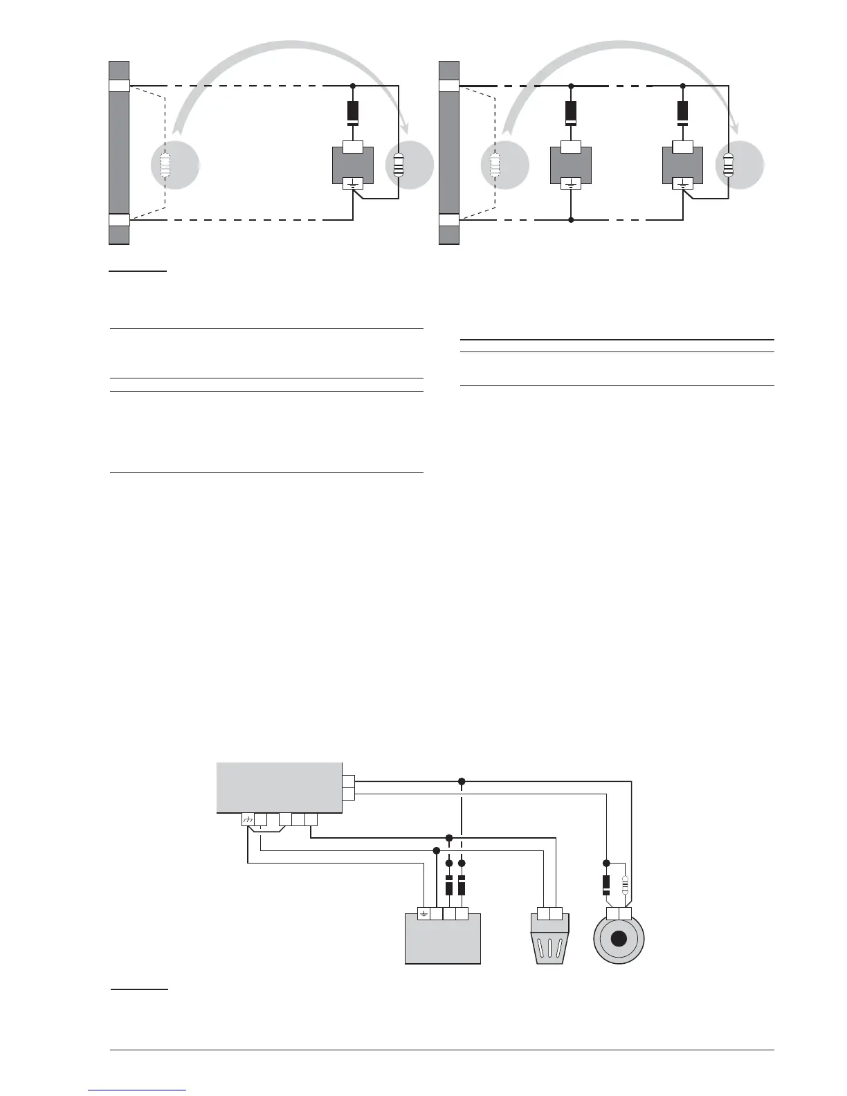
For example, a connection similar to the wiring diagram
in figure 12 will activate the Flasher, the Bell and the vi-
sual and audible signalling device of the Self-powered
Siren in the event of an alarm.
Using the SILENCE button will stop the horn but not the
flasher, which will continue to signal Alarm status until
the RESET button is pressed.
Connecting a Power Supply
+
The power circuits of this Control panel comply
with the EN54-4 standard.
!
In order to comply with the Safety regulations
in force, the Mains must be equipped with a bi
-
polar isolating device for protection against
over voltage and short-circuit to Earth (e.g. au
-
tomatic isolating switch).
This Control panel is powered from the Mains
(110/230V~ 60/50 Hz) through a Switching power
supply, located inside the case. The FC510 and
FC520 Control panel provide housing for two 12 V, 17
Ah maximum batteries;
moreover, the FC510 and FC520 Control panel can be
connected to two 12 V, 38 Ah in an external metal box
(see Figure 15) for power during Mains failure.
The non-volatile memory will hold the programmed data
at all times.
In the event of Mains failure, the:
Ø
GREEN Mains LED will turn OFF
Ø
AMBER Mains LED will turn ON
24 Addressable Fire Control Panels FC500