Installing the 38Ah battery metal Box
Work carefully through the following steps (see Figure
16).
1. Remove the screws (2) and open the metal box.
2. Drill the anchor screw holes.
!
Check for water pipes and electrical wiring be
-
fore drilling.
3. If necessary, using a hammer or similar tool, remo
-
ve the surface conduit wire knockouts 1.
4. Secure the metal backplate to the wall
+
The cable conduit union with the case must be se
-
cured by HB Flame Class (or higher) lock nuts.
Pull the wires through the chased wire entry 1 and con
-
nect them. See paragraph: Connecting a power supply.
Maintenance
The following operations must be carried out regularly.
A Using a damp cloth (DO NOT USE SOLVENTS OF
ANY KIND), remove dust from the Control panel case.
B
Using the Lamp/Buzz/Test key, check that the
LEDs and buzzer are functioning properly.
C Ensure that the batteries are sufficiently charged and
functioning properly. If not, replace them immediately.
D Ensure that all cables and connections are intact.
E Ensure that there are no unrelated objects inside the
Control panel case.
+
Points A and B may be carried out by users.
Points C, D and E must be carried out by qualified
persons only.
INSTALLATION 27
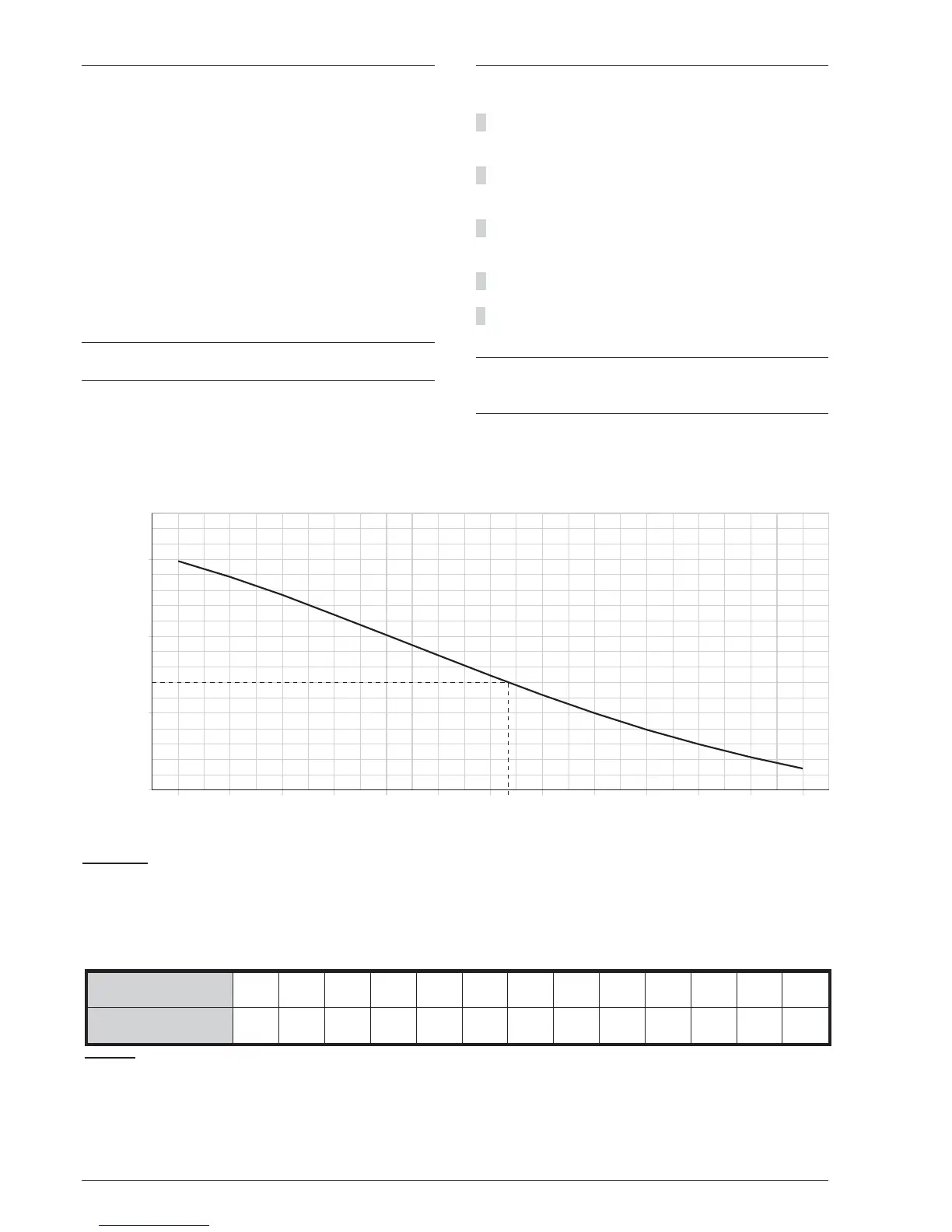
Figure 17 Switching Power Supply Output Voltage graph. To find the Output Voltage using the graph: — indicate the
Probe temperature on the TEMPERATURE (°C) axis; draw a line from the temperature value point up to the curve a);
draw a line from the intersection point across to the VOLTAGE (V) axis; adjust the Output Voltage of the Switching Po
-
wer Supply to the resultant value. For example, if the Probe temperature is 22 °C, the Output Voltage of the Switching
Power Supply must be set at 27.4 V.
TEMPERATURE (°C) -10 -5 0 5 10 15 20 25 30 35 40 45 50
VOLTAGE (V) 29,0 28,8 28,6 28,2 28,0 27,8 27,4 27,2 27,0 26,8 26,6 26,4 26,2
Table 5 Switching Power Supply Output Voltage chart. To find the Output Voltage using the chart: — select the nea
-
rest value to the Probe temperature on the TEMPERATURE (°C) row; read the respective value on the VOLTAGE (V)
row; adjust the Output Voltage of the Switching Power Supply to the indicated value. For example, if the Probe tempe
-
rature is 22 °C, the Output Voltage of the Switching Power Supply must be set at 27.4 V.