Maintenance
TROUBLESHOOTING
-
and output lands can cause small errors that are not related
to resistor networks. Load regulation problems can also
be
caused by shorts between sense and load lines.
In some rare cases, the op amps (U702A and U702B)
could be out of spec, causing
a
small error.
The:
maximum
input offset voltage of the op amps used in the circuit is 3
mV.
6-66.
AID
Converter Troubles hooting
If there is
a
failure of the
A/D
Converter, all power supply
levels should
be
checked at the op amps (U102 and U103)
and the
AD
IC (U101). The
AID
Converter has a total of
seven supplies: +15V, -15V, +5V, +7.5V, -8.2V7
+7.00000V7 and
-7.00000V.
All supplies should
be
within
5%
of their nominal values except for the +7.CtWOOV and
-7.00000V reference supplies, which should
be
within
d000
pprn
and 2250 ppm respectively. The bootstrap
supplies (lines BS1 and BS2) should be +7\r and -7V
(210%) referenced to the
+
input of the
A/D
amplifier
(U103-3).
Troubleshooting the bootstrap supplies can often be made
easier by putting the 8840A in
EX
TRIG (to stop the
A/D
Converter) and connecting the input of the
AID
Converter
(TP103) to INPUT
LO
(Reference Low on the schematic).
The
bootstrap supplies are then referenced to instrument
common (Reference Low).
NOTE
For the following tests, set the
8840A
to the
VDC
function
and
the
2V
range,
and
trigger
the oscilloscope
from
the falling edge of line
not-TR
(TP201).
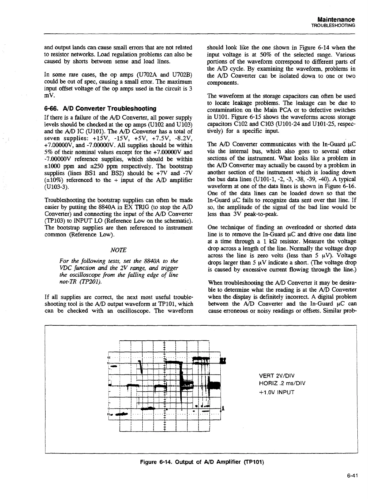
If
all supplies are correct, the next most useful trouble-
shooting tool is the
AID
output waveform at TP101, which
can be checked with an oscilloscope. The waveform
should look like the one Shown in Figure 6-14 when the
input voltage is at 50% of the selected range. Various
portions of the waveform
correspond to different parts of
the
AID
cycle. By examining the waveform, problems in
the
A/D
Converter can
be
isolated down to one or two
components.
The waveform at the storage capacitors can often be used
to locate leakage problems. The leakage can
be
due to
contamination on the
Main
PCA or to defective switches
in U101. Figure 6-15 shows the waveforms across storage
capacitors C102 and C103 (U101-24 and U101-25, respec-
tively) for a specific input.
The
A/D
Converter communicates with the In-Guard
pC
via the internal bus, which also goes to several other
sections of the instrument. What looks like a problem in
the
AID
Converter may actually
be
caused
by
a problem in
another section of the instrument which is loading down
the bus data lines (U101-1, -2, -3, -38, -39,
-40).
A typical
waveform at one of the
data
lines is shown in
Figure
6-16.
One of the data lines can be loaded down
so
that the
In-Guard pC fails to recognize data sent over that lline. If
so, the amplitude of the signal of the bad line would
be
less than 3V peak-to-peak.
One technique of finding an overloaded or shorted data
line is to remove the In-Guard pC and drive one data line
at a time through a
1
kQ
resistor. Measure the voltage
drop across a length of the line. Normally the voltage drop
across the line is zero volts (less than
5
yV). Voltage
drops larger than
5
WV indicate a short. (The voltage drop
is caused by excessive current flowing through
the:
line.)
When troubleshooting the
AID
Converter it may
be
desira-
ble to determine what the reading is at the
AID
Converter
when the display is definitely incorrect.
A
digital problem
between the
A/D
Converter and the In-Guard pC can
cause erroneous or noisy readings or offsets. Similar prob-
VERT 2V/DIV
HORIZ
.2
ms/DIV
+1
.OV
INPUT
Figure
6-14.
Output
of
A/D
Amplifier
(rP101)
Artisan Technology Group - Quality Instrumentation ... Guaranteed | (888) 88-SOURCE | www.artisantg.com