Introdu$tion
and
specifications
SPECIFICA~IONS
Table
1-1.
Specifications (cont)
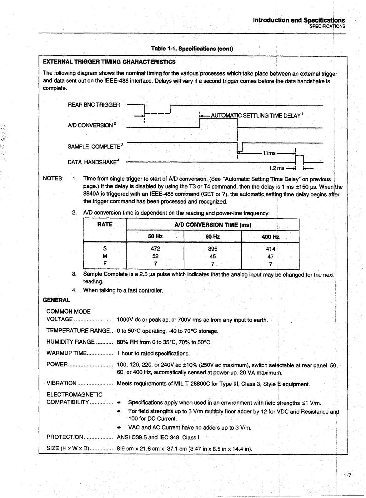
EXTERNAL TRIGGER TIMING CHARACTERISTICS
The following diagram shows the nominal timing for the various processes which take place between an external trigger
and data sent out on the IEEE-488 interface. Delays will vary if a second trigger comes before the data handshake is
complete.
REAR BNC TRIGGER
7--J
-i
AUTOMATIC SETnlNG TIME DELAY'
AID
COMlERSlON
*
I
!
!
SAMPLE COMPLETE
I
-11ms-
!
DATA
HANDSHAKE^
I
I
1.2ms-d
!-
NOTES:
1.
Time from single trigger to start of AID conversion. (See "Automatic Setting Time Delay" on previous
page.)
If
the delay is disabled by using the T3 or T4 command, then the delay is 1 ms +I50
~LS.
When the
8840A is triggered with an IEEE-488 command (GET or ?), the automatic setting time delay begins aftbr
the trigger command has been processed and recognized.
2. AID conversion time is dependent on the reading and power-line frequency:
r
RATE
AID
CONVERSION TIME
(ms)
50Hz
60Hz
400&
S
472
395 41 4
M 52
45 47
F
7
7 7
3. Sample Complete is a 2.5
ps
pulse which indicates that the analog input may
tie
changed for the next
reading.
4.
When talking to a fast controller.
GENERAL
COMMON MODE
.........................
VOLTAGE
1000V dc or peak ac, or 700V rrns ac from any input to earth.
TEMPERATURE RANGE.. 0 to 50°C operating,
-40
to 70% storage.
HUMIDITY RANGE
...........
80% RH from 0 to 35"C, 70% to 50°C.
WARMUP TIME
.................
1 hour to rated specifications.
POWER
.............................
100, 120, 220, or 240V ac
+I
0% (250V ac maximum), switch selectable at rear panel,
50
60, or 400
Hz,
automatically sensed at power-up. 20 VA maximum.
VIBRATION
.......................
Meets requirements of MIL-T-28800C for Type
Ill,
Class 3, Style
E
equipment.
ELECTROMAGNETIC
...............
COMPATIBILITY
Specifications apply when used in an environment with field strengths 51 V/m.
For field strengths up to
3
V/m multiply floor adder by
12
for VDC and Resistance
a
100 for
DC
Current.
VAC and AC Current have no adders up to
3
V/m.
...................
PROTECTION
ANSI C39.5 and
IEC
348,
Class
I.
Artisan Technology Group - Quality Instrumentation ... Guaranteed | (888) 88-SOURCE | www.artisantg.com