MC68332 QUEUED SERIAL MODULE
USER’S MANUAL 6-1
SECTION 6 QUEUED SERIAL MODULE
This section is an overview of queued serial module (QSM) function. Refer to the
QSM
Reference Manual
(QSMRM/AD) for complete information about the QSM.
6.1 General
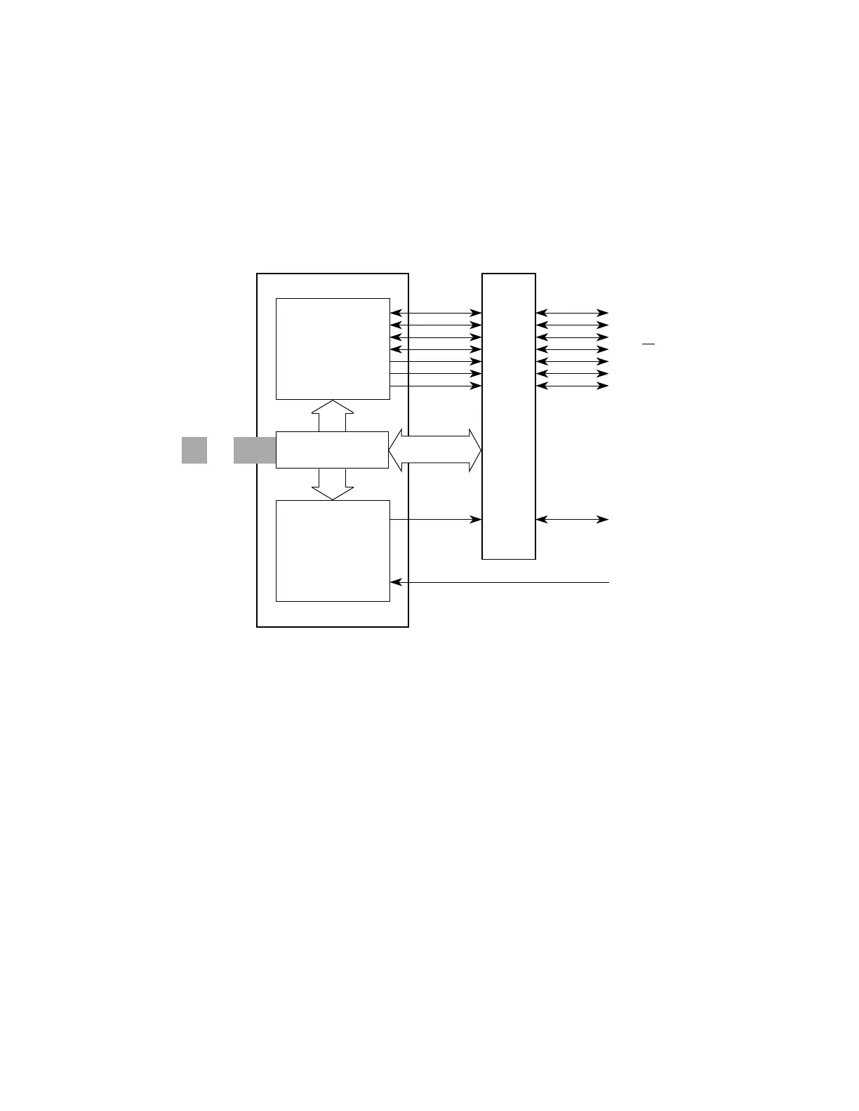
The QSM contains two serial interfaces, the queued serial peripheral interface (QSPI)
and the serial communication interface (SCI). Figure 6-1 is a block diagram of the
QSM.
Figure 6-1 QSM Block Diagram
The QSPI provides easy peripheral expansion or interprocessor communication
through a full-duplex, synchronous, three-line bus. Four programmable peripheral chip
selects can select up to 16 peripheral devices. A self-contained RAM queue allows up
to sixteen serial transfers of eight to sixteen bits each or transmission of a 256-bit data
stream without CPU intervention. A special wraparound mode supports continuous
sampling of a serial peripheral, with automatic QSPI RAM updating, for efficient inter-
facing to A/D converters.
The SCI provides a standard nonreturn to zero (NRZ) mark/space format. It will oper-
ate in either full- or half-duplex mode. There are separate transmitter and receiver en-
able bits and dual data buffers. A modulus-type baud rate generator provides rates
from 64 to 524 kbaud with a 16.78-MHz system clock, or 110 to 655 kbaud with a
20.97-MHz system clock. Word length of either eight or nine bits can be selected. Op-
tional parity generation and detection provide either even or odd parity check capabil-
QSPI
INTERFACE
LOGIC
SCI
MISO/PQS0
MOSI/PQS1
SCK/PQS2
PCS0/SS
/PQS3
PCS1/PQS4
PCS2/PQS5
PCS3/PQS6
TXD/PQS7
RXD
PORT QS
QSM BLOCK
IMB
Fr
ees
cale S
em
iconduct
or
, I
Freescale Semiconductor, Inc.
For More Information On This Product,
Go to: www.freescale.com
nc...