MC68332 OVERVIEW
USER’S MANUAL 3-15
3.7 System Reset
The following information is a concise reference only. MC68332 system reset is a com-
plex operation. To understand operation during and after reset, refer to SECTION 4
SYSTEM INTEGRATION MODULE, paragraph 4.6 Reset for more complete discus-
sion of the reset function.
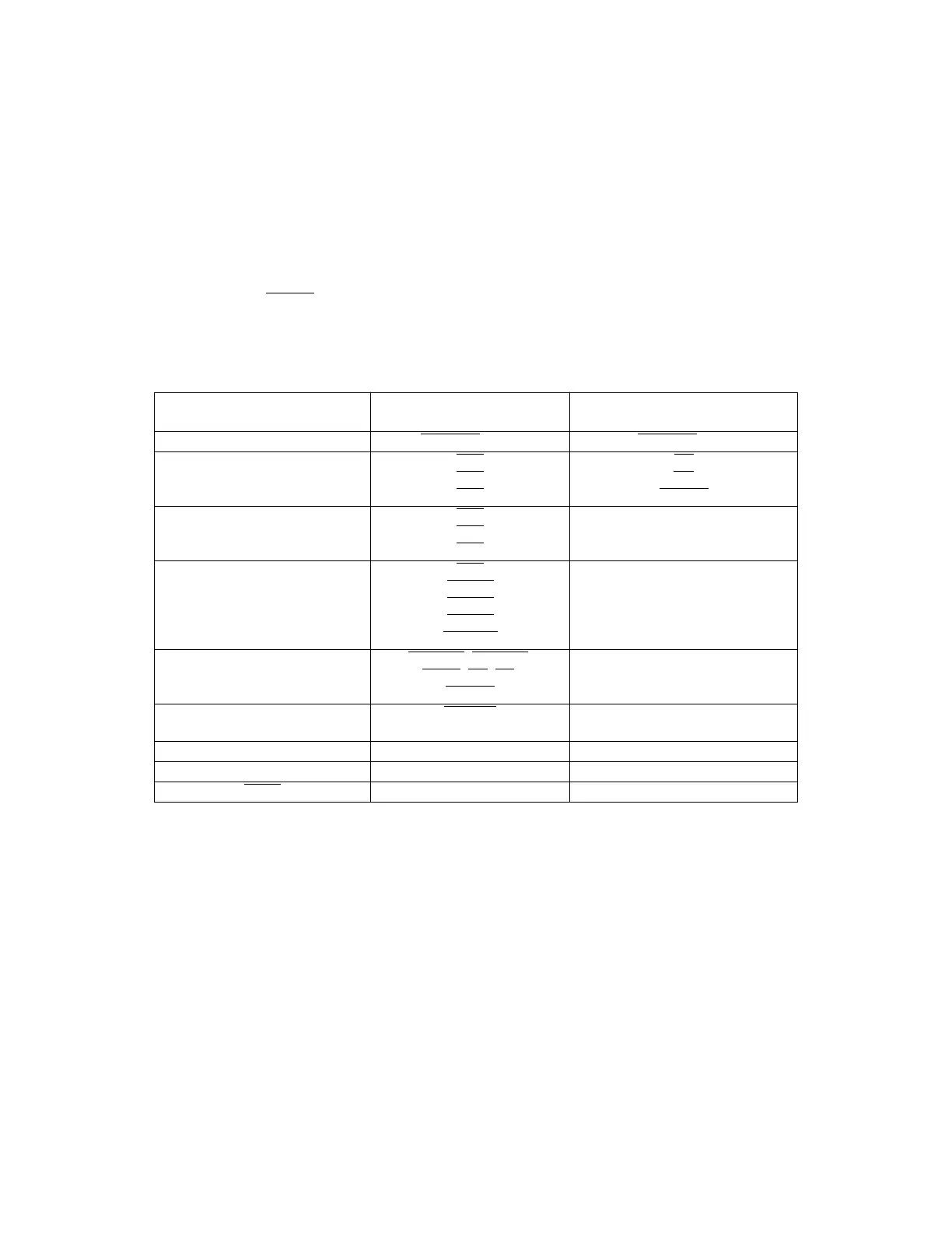
3.7.1 SIM Reset Mode Selection
The logic states of certain data bus pins during reset determine SIM operating config-
uration. In addition, the state of the MODCLK pin determines system clock source and
the state of the BKPT
pin determines what happens during subsequent breakpoint as-
sertions. Table 3-6 is a summary of reset mode selection options.
Table 3-6 SIM Reset Mode Selection
Mode Select Pin Default Function
(Pin Left High)
Alternate Function
(Pin Pulled Low)
DATA0 CSBOOT
16-Bit CSBOOT 8-Bit
DATA1 CS0
CS1
CS2
BR
BG
BGACK
DATA2 CS3
CS4
CS5
FC0
FC1
FC2
DATA3
DATA4
DATA5
DATA6
DATA7
CS6
CS[7:6]
CS[8:6]
CS[9:6]
CS[10:6]
ADDR19
ADDR[20:19]
ADDR[21:19]
ADDR[22:19]
ADDR[23:19]
DATA8 DSACK0
, DSACK1,
AVEC
, DS, AS,
SIZ[1:0]
PORTE
DATA9 IRQ[7:1]
MODCLK
PORTF
DATA11 Test Mode Disabled Test Mode Enabled
MODCLK VCO = System Clock EXTAL = System Clock
BKPT
Background Mode Disabled Background Mode Enabled
Fr
ees
cale S
em
iconduct
or
, I
Freescale Semiconductor, Inc.
For More Information On This Product,
Go to: www.freescale.com
nc...