MC68332 SYSTEM INTEGRATION MODULE
USER’S MANUAL 4-19
4.4.1.6 Size Signals
Size signals (SIZ[1:0]) indicate the number of bytes remaining to be transferred during
an operand cycle. They are valid while the address strobe (AS
) is asserted. Table 4-
10 shows SIZ0 and SIZ1 encoding.
4.4.1.7 Function Codes
The CPU generates function code output signals FC[2:0] to indicate the type of activity
occurring on the data or address bus. These signals can be considered address ex-
tensions that can be externally decoded to determine which of eight external address
spaces is accessed during a bus cycle.
Address space 7 is designated CPU space. CPU space is used for control information
not normally associated with read or write bus cycles. Function codes are valid while
AS
is asserted.
Table 4-11 shows address space encoding.
The supervisor bit in the status register determines whether the CPU is operating in
supervisor or user mode. Addressing mode and the instruction being executed deter-
mine whether a memory access is to program or data space.
4.4.1.8 Data and Size Acknowledge Signals
During normal bus transfers, external devices assert the data and size acknowledge
signals (D
SACK[1:0]) to indicate port width to the MCU. During a read cycle, these sig-
nals tell the MCU to terminate the bus cycle and to latch data. During a write cycle, the
signals indicate that an external device has successfully stored data and that the cycle
can terminate. DSACK[1:0]
can also be supplied internally by chip-select logic. Refer
to 4.8 Chip Selects for more information.
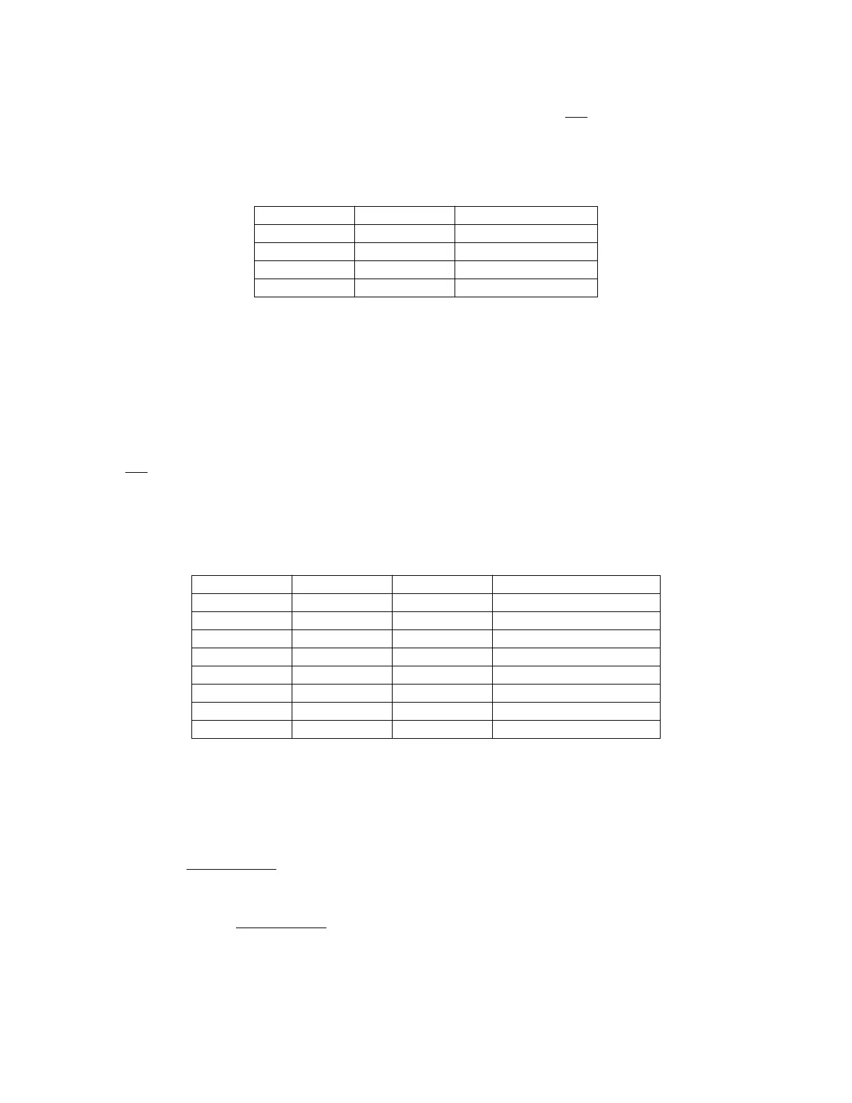
Table 4-10 Size Signal Encoding
SIZ1 SIZ0 Transfer Size
0 1 Byte
1 0 Word
1 1 3 Byte
0 0 Long Word
Table 4-11 Address Space Encoding
FC2 FC1 FC0 Address Space
0 0 0 Reserved
0 0 1 User Data Space
0 1 0 User Program Space
0 1 1 Reserved
1 0 0 Reserved
1 0 1 Supervisor Data Space
1 1 0 Supervisor Program Space
1 1 1 CPU Space
Fr
ees
cale S
em
iconduct
or
, I
Freescale Semiconductor, Inc.
For More Information On This Product,
Go to: www.freescale.com
nc...