MC68332 SYSTEM INTEGRATION MODULE
USER’S MANUAL 4-39
4.6.3.1 Data Bus Mode Selection
All data lines have weak internal pull-up drivers. When pins are held high by the inter-
nal drivers, the MCU uses a default operating configuration. However, specific lines
can be held low externally to achieve an alternate configuration.
NOTE
External bus loading can overcome the weak internal pull-up drivers
on data bus lines, and hold pins low during reset.
Use an active device to hold data bus lines low. Data bus configuration logic must re-
lease the bus before the first bus cycle after reset to prevent conflict with external
memory devices. The first bus cycle occurs ten CLKOUT cycles after RESET
is re-
leased. If external mode selection logic causes a conflict of this type, an isolation re-
sistor on the driven lines may be required. Figure 4-15 shows a recommended method
for conditioning the mode select signals.
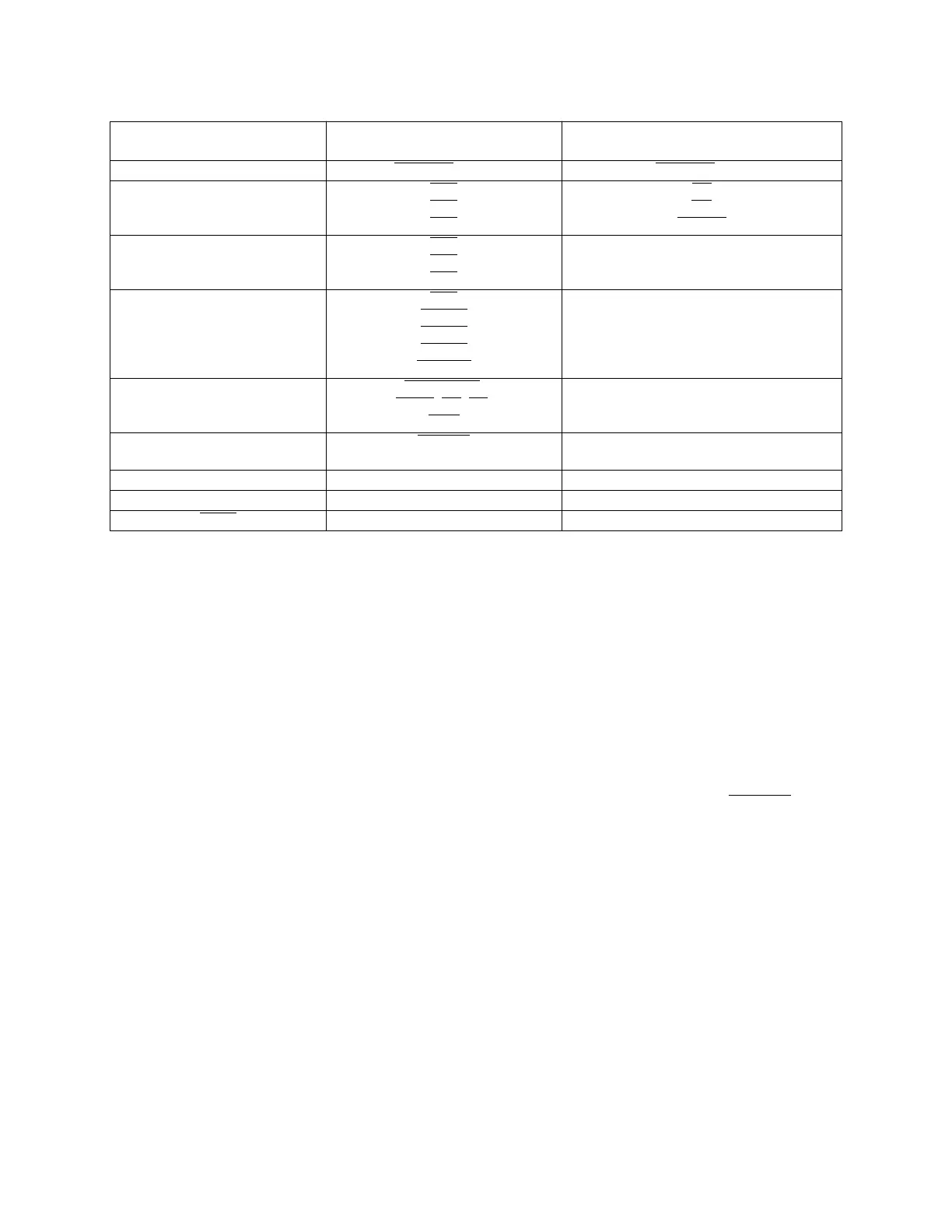
Table 4-16 Reset Mode Selection
Mode Select Pin Default Function
(Pin Left High)
Alternate Function
(Pin Pulled Low)
DATA0 CSBOOT
16-Bit CSBOOT 8-Bit
DATA1 CS0
CS1
CS2
BR
BG
BGACK
DATA2 CS3
CS4
CS5
FC0
FC1
FC2
DATA3
DATA4
DATA5
DATA6
DATA7
CS6
CS[7:6]
CS[8:6]
CS[9:6]
CS[10:6]
ADDR19
ADDR[20:19]
ADDR[21:19]
ADDR[22:19]
ADDR[23:19]
DATA8 DSACK[1:0]
,
AVEC
, DS, AS,
SIZE
PORTE
DATA9 IRQ[7:1]
MODCLK
PORTF
DATA11 Test Mode Disabled Test Mode Enabled
MODCLK VCO = System Clock EXTAL = System Clock
BKPT
Background Mode Disabled Background Mode Enabled
Fr
ees
cale S
em
iconduct
or
, I
Freescale Semiconductor, Inc.
For More Information On This Product,
Go to: www.freescale.com
nc...