SYSTEM INTEGRATION MODULE MC68332
4-40 USER’S MANUAL
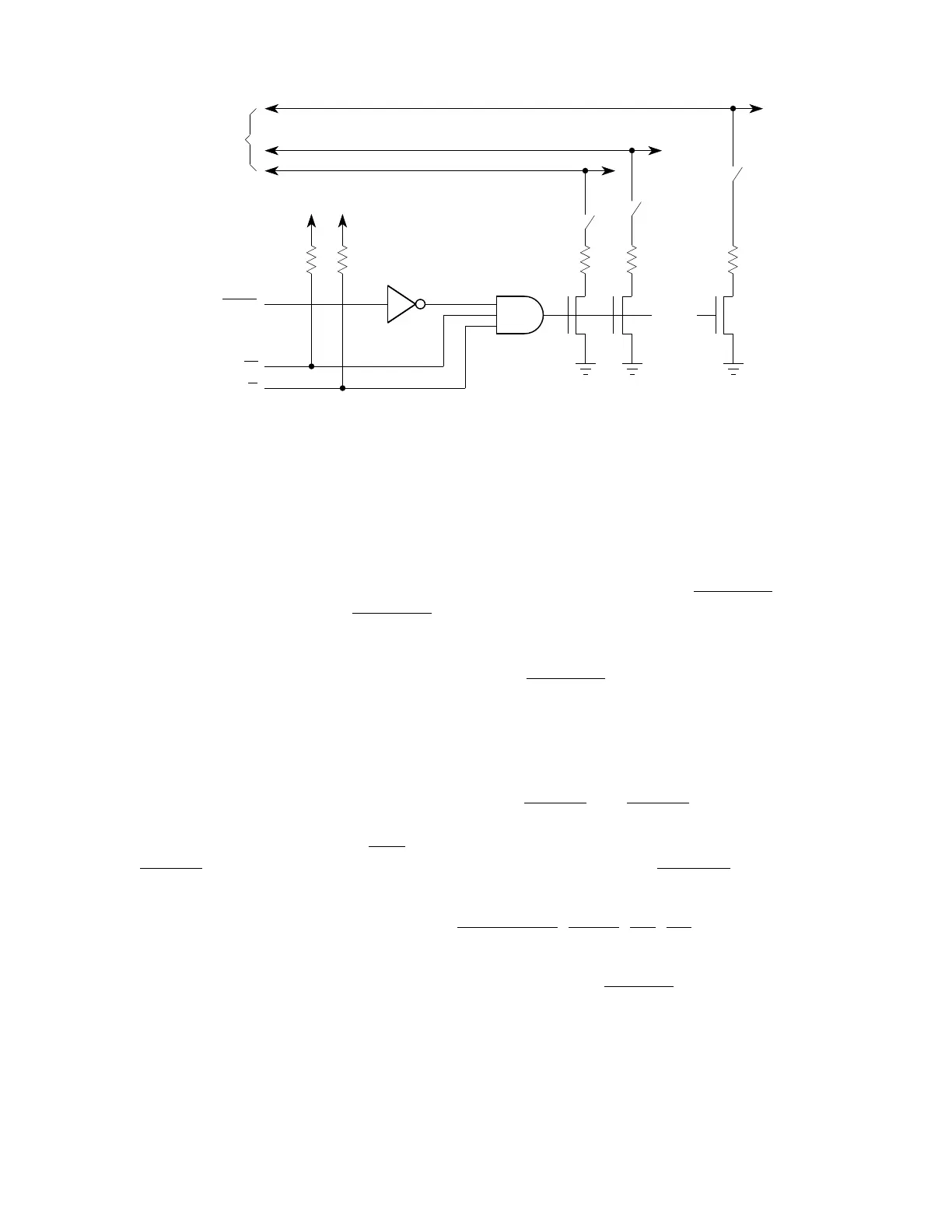
Figure 4-15 Data Bus Mode Select Conditioning
Data bus mode select current is specified in APPENDIX A ELECTRICAL CHARAC-
TERISTICS. Do not confuse pin function with pin electrical state. Refer to 4.6.5 Pin
State During Reset for more information.
DATA0 determines the function of the boot ROM chip-select signal (CSBOOT
). Unlike
other chip-select signals, C
SBOOT is active at the release of reset. During reset ex-
ception processing, the MCU fetches initialization vectors beginning at address
$000000 in supervisor program space. An external memory device containing vectors
located at these addresses can be enabled by CSBOOT
after a reset. The logic level
of DATA0 during reset selects boot ROM port size for dynamic bus allocation. When
DATA0 is held low, port size is eight bits; when DATA0 is held high, either by the weak
internal pull-up driver or by an external pull-up, port size is 16 bits. Refer to 4.8.4 Chip-
Select Reset Operation for more information.
DATA1 and DATA2 determine the functions of CS[2:0]
and CS[5:3], respectively. DA-
TA[7:3] determine the functions of an associated chip select and all lower-numbered
chip-selects down through CS6
. For example, if DATA5 is pulled low during reset,
CS[8:6]
are assigned alternate function as ADDR[21:19], and CS[10:9] remain chip-
selects. Refer to 4.8.4 Chip-Select Reset Operation for more information.
DATA8 determines the function of the DSACK[1:0]
, AVEC, DS, AS, and SIZE pins. If
DATA8 is held low during reset, these pins are assigned to I/O port E.
DATA9 determines the function of interrupt request pins IRQ[7:0]
and the clock mode
select pin (MODCLK). When DATA9 is held low during reset, these pins are assigned
to I/O port F.
DATA11 determines whether the SIM operates in test mode out of reset. This capabil-
ity is used for factory testing of the MCU.
•
•
•
•
•
•
•
•
•
•
•
•
•
•
•
•
•
•
DATA BUS MODE DECODE
RESET
R/W
MODE SELECT
LINES
DS
V
DD
V
DD
DATA15
DATA1
DATA0
* * *
*Optional, to prevent conflict on RESET negation.
Fr
ees
cale S
em
iconduct
or
, I
Freescale Semiconductor, Inc.
For More Information On This Product,
Go to: www.freescale.com
nc...