MC68332 SYSTEM INTEGRATION MODULE
USER’S MANUAL 4-45
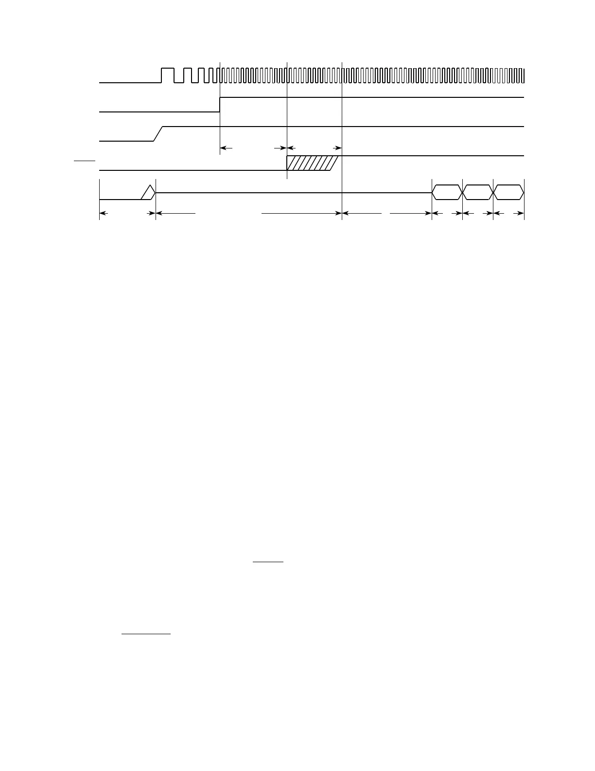
Figure 4-16 Power-On Reset
4.6.8 Reset Processing Summary
To prevent write cycles in progress from being corrupted, a reset is recognized at the
end of a bus cycle, and not at an instruction boundary. Any processing in progress at
the time a reset occurs is aborted. After SIM reset control logic has synchronized an
internal or external reset request, it asserts the MSTRST signal.
The following events take place when MSTRST is asserted.
A. Instruction execution is aborted.
B. The status register is initialized.
1. The T0 and T1 bits are cleared to disable tracing.
2. The S bit is set to establish supervisor privilege level.
3. The interrupt priority mask is set to $7, disabling all interrupts below priority
7.
C. The vector base register is initialized to $000000.
The following events take place when MSTRST is negated after assertion.
A. The CPU32 samples the BKPT
input.
B. The CPU32 fetches the reset vector:
1. The first long word of the vector is loaded into the interrupt stack pointer.
2. The second long word of the vector is loaded into the program counter.
Vectors can be fetched from internal RAM or from external ROM enabled by the
CSBOOT
signal.
C. The CPU32 fetches and begins decoding the first instruction to be executed.
32 POR TIM
CLKOUT
VCO
LOCK
BUS
CYCLES
RESET
V
DD
1
BUS STATE
UNKNOWN
ADDRESS AND
CONTROL SIGNALS
THREE-STATED
512 CLOCKS
NOTES:
1. Internal start-up time.
2. SSP fetched.
3. PC fetched.
4. First instruction fetched.
10 CLOCKS
4
32
Fr
ees
cale S
em
iconduct
or
, I
Freescale Semiconductor, Inc.
For More Information On This Product,
Go to: www.freescale.com
nc...