QUEUED SERIAL MODULE MC68332
6-26 USER’S MANUAL
• Start Bit — One bit-time of logic zero that indicates the beginning of a data frame.
A start bit must begin with a one-to-zero transition and be preceded by at least
three receive time (RT) samples of logic one.
• Stop Bit — One bit-time of logic one that indicates the end of a data frame.
• Frame — A complete unit of serial information. The SCI can use 10-bit or 11-bit
frames.
• Data Frame — A start bit, a specified number of data or information bits, and at
least one stop bit.
• Idle Frame — A frame that consists of consecutive ones. An idle frame has no
start bit.
• Break Frame — A frame that consists of consecutive zeros. A break frame has
no stop bits.
6.4.3.2 Serial Formats
All data frames must have a start bit and at least one stop bit. Receiving and transmit-
ting devices must use the same data frame format. The SCI provides hardware sup-
port for both ten-bit and eleven-bit frames. The serial mode (M) bit in SCI control
register one (SCCR1) specifies the number of bits per frame.
The most common ten-bit data frame format for NRZ serial interface consists of one
start bit, eight data bits (LSB first), and one stop bit. The most common eleven-bit data
frame contains one start bit, eight data bits, a parity or control bit, and one stop bit.
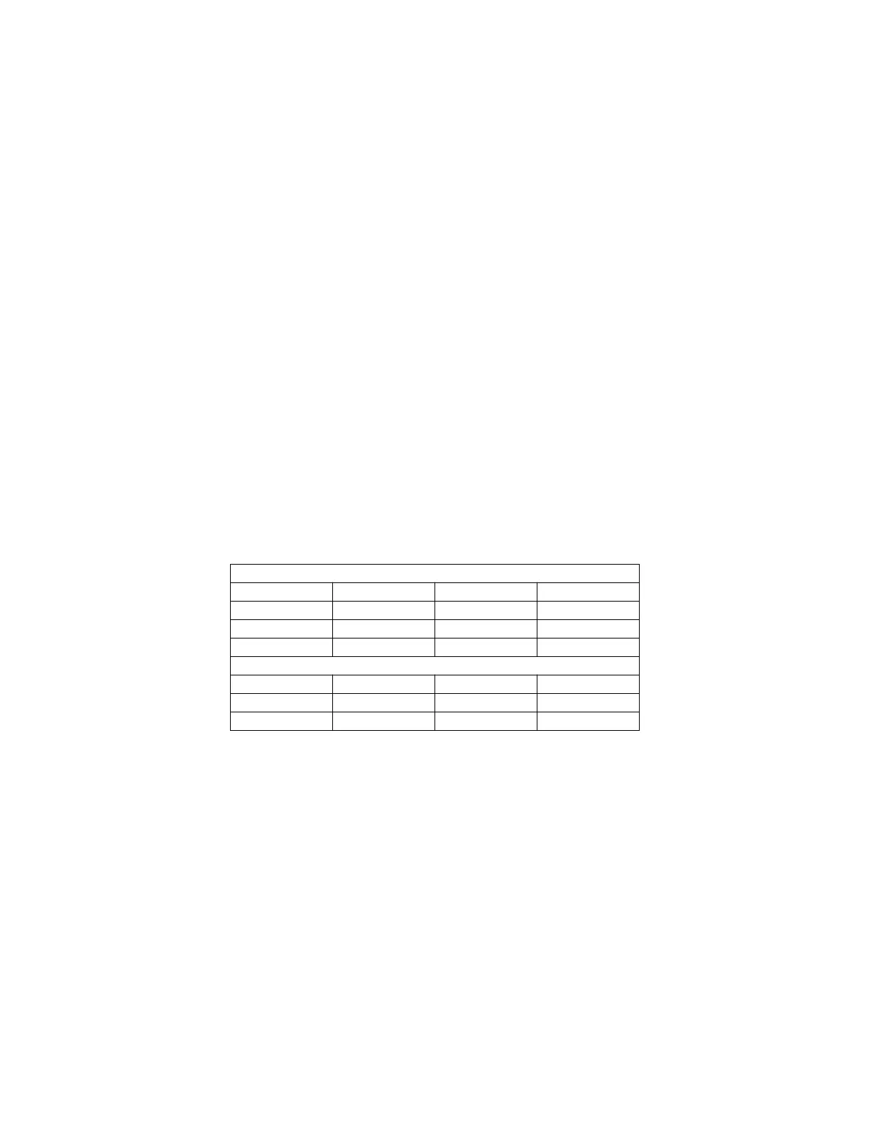
Ten-bit and eleven-bit frames are shown in Table 6-5.
6.4.3.3 Baud Clock
The SCI baud clock is programmed by writing a 13-bit value to the baud rate (SCBR)
field in SCI control register zero (SCCR0). Baud clock is derived from the MCU system
clock by a modulus counter. Writing a value of zero to SCBR disables the baud rate
generator. Baud clock rate is calculated as follows:
where SCBR is in the range {1, 2, 3,..., 8191}.
The SCI receiver operates asynchronously. An internal clock is necessary to synchro-
nize with an incoming data stream. The SCI baud clock generator produces a receive
Table 6-5 Serial Frame Formats
10-Bit Frames
Start Data Parity/Control Stop
1 7—2
1711
1 8—1
11-Bit Frames
Start Data Parity/Control Stop
1712
1811
SCI Baud Clock Rate
System Clock
32 SCBR×
------------------------------------=
Fr
ees
cale S
em
iconduct
or
, I
Freescale Semiconductor, Inc.
For More Information On This Product,
Go to: www.freescale.com
nc...